EN
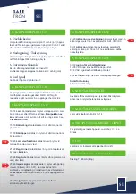
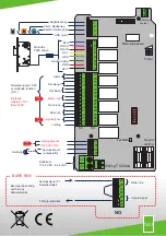
2. Emergency opening / Timer connection
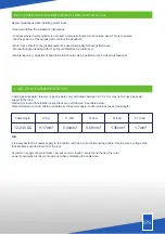
Conected to ground ( terminal 2 and 4 )the dead bolt will
immiediately go to its retracted / unlocked position and
remain there until disconnection.
3. Door magnet switch
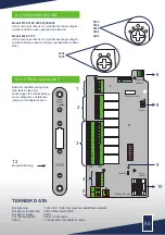
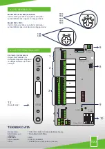
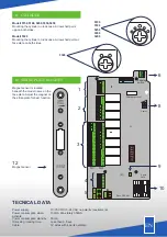
1. TERMINAL 1-4
2. TERMINAL 5-12
4. TERMINAL 28-31
5. TERMINAL 32-33
6. SABOTAGE SWITCH
7. SABOTAGE PROTECTED CABLE
8. POTENTIOMETER / OPENTIME
9. ON
1. Dayblocking
Activating signal between terminal 1 and 4 (gnd) opens the
lock when its activated between terminal 30 and 31 or 28
and 29 then the dead bolt remains in its retracted position
until disconnection.
For use with an external door magnet switch.
e.g. when using an external magnet placed in the door
header. Terminals 3 and 4 (gnd)
4. Ground (gnd)
Use together with terminals 1-3
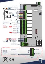
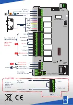
Terminals 5-12 connect the 11 wire cable to the lock case
as per colour marking.
NOTE
correct colour in correct
position. See wire diagram page 4
3. TERMINAL 13-27
13-14
Alarm Switch
closes/opens when door is open
for more then 2 min or 8 cycles to lock.
15-16
Door closed
Switch closes/when door magnet is
activated ( door closes )
17-18
Door open
Switch/opens when door magnet not
is deactivated ( door opens )
19-20
Pre alarm
Switch closes/opens before alarm
(terminals 13-14 ) for example when dead bolt is blocked
21-22
Dead bolt in
Switch closes/opens when bolt is
unlocked.
23-24
Dead bolt out
Switch closes/opens when bolt is
locked.
25-26
Impuls signal
Switch closes/opens when
activating terminals 30,31 Can be used to an electrik
strikes when dayblocking is needed. To activate
dooropener connects together with bolt in 21,22. see
example in wiring diagram.
27
Ground
Connect to ground to eliminate external
disturbance.
28-29
Activating with power
Activates lock with a
power impuls as an exampel a card reader with a built in
feeding voltage 8-24 VAC /DC
30-31
Activating
Aktivates lock via potential free
connection between terminal 30 and 31 as exampel card
reader, key switch, code reader.
32-33
Input power supply
10-35 VDC no polarity requirement
8-24 VAC no polarity requirement.
Terminal
B.
Output voltage = same as power supply
Powerconsumption when activated
150mA on activation.
Used to monitor the controller. Micro switch is activated
when the controll unit lid is removed.
Prealarm for cable satotage. Terminal 13-14
Used for adjusting opentime , t = 1 - 30 sec.
LED power indicator
10. MAIN FUSE/ SPARE FUSE
Slow fuse 500mA
EN
ONLY
5000
ONLY
5000
ONLY
5000
ONLY
5000

