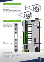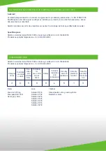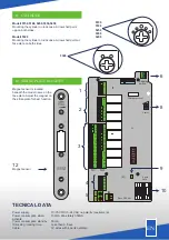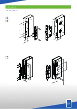
11. CYLINDER
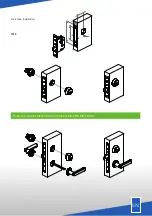
12. STRIKE PLATE MAGNET
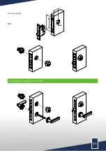
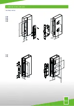
Modell 5150,5188, 5250,5350,5450
Mounting the cylinder on lock case. Arrow shall point
upp on both sides.
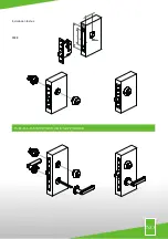
Modell 5328
Mounting the cylinder on lock case. Arrow shall point at
face plate on both sides.
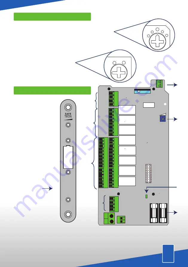
TECNICAL DATA
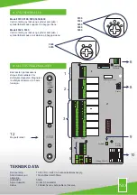
Magnet sensor is located
beneath the model name on the
face plate. Adjust the magnet on
the strike plate for best function.
Magnet sensor
12
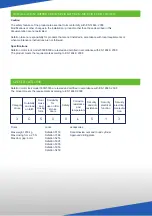
Power supply.
Power consumption when
activate.
Power consumption standby.
Unlocking / locking time.
Cable.
10-35 VDC / 8-24 VAC no polarity requirements
150mA Max totaly 350mA
50mA
Less then 0,5 sec
12 wires with 4 parts availible
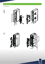
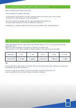
5150
5188
5250
5350
5450
5328
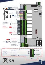
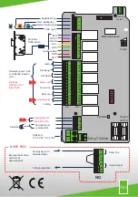
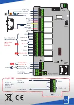
Sabotage
switch
Microprocessor
1
2
3
4
5
6
7
8
9
10
11
13
14
15
16
17
18
19
20
21
30
29
31
Timer
LED
Spare
fuse
Fuse 500 mA
1
2
3
6
8
10
12
22
23
25
24
27
26
28
4
13
14
15
16
17
18
19
20
21
22
23
25
24
27
26
32
33
9
5
NC
NO
B
EN
5350

