Car lift installation, operation and maintenance manual Type
:
4SF-4000B
14
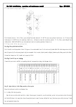
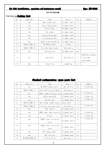
17.1 Installation of gas path elements
1.
24V electronic valve
2.
1/4-
¢
8mm quick straight head tracheal joint
3.
M4*35 cross recessed pan head screw
4.
Y
¢
8mm quick
tracheal joint
5.
M4*20 cross recessed pan head screw
6.
Single connection oil-water separator
7.
1/4-
¢
8mm quick straight head
tracheal joint
8.9.10.11
M6*16 cross recessed pan head screw,spring washers, flat pad, nut
17.2 Connection of the gas path system
Step 18
:
Fill up with hydraulic fluid:
Note: when the actual temperature is above 18 degrees, it is recommended to use No. 46 anti-wear hydraulic fluid. When the temperature is lower
than 18 degrees, No.32 anti-wear hydraulic oil is recommended. The viscosity of the hydraulic oil largely determines the lifting speed of the lifter.
The tank has a capacity of 10L, usually only a capacity of 80%.
Step 19
:
Connect the power supply
;
Connect the power source and the corresponding electrical components according to the diagram below
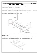
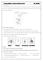
Step 20: Adjust the level of the lifting machine at four points
Please do not place any vehicle in adjustment time
A
:
Leveling of the whole machine
Open the power switch on the control box, release the emergency stop switch, press the up button, such as wire rope tension after all, measure
the 2 end of the beam to the main side column base plate distance is equal, if not equal, adjust the top of the column nut until the wire rope 2 beam
four end end plate distance line.
Pow
er
cor
d
G
roun
d
w
ir
e
G
roun
d
w
ir
e
Mot
or
l
ine
U
pper
l
im
it l
ine
T
w
o f
al
l l
im
it l
ine


