Page x
LIST OF ILLUSTRATIONS
Figure
Page
1
Vector diagram.................................................................................................................................
3
2
Detector coil system signals ............................................................................................................
4
3
Effect of phase control .....................................................................................................................
4
4
Effect of phase control adjustment ..................................................................................................
4
5
Metal Free Zone Guidelines - Standard Series Detectors ...............................................................
5
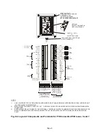
6A
Layout of Components and Terminals for P/S Connection PCB issues - 6 and 7 ..........................
8
6B
Power connections...........................................................................................................................
9
6C
Cable Gland Assemblies for Power Supply Units............................................................................
9A
7
Roller Shaft Insulation ......................................................................................................................
9B
8
Bearing Block Insulation ..................................................................................................................
9B
9
Mounting Foot Insulation..................................................................................................................
10
10
Belt Joints.........................................................................................................................................
10
11
Control Panel ...................................................................................................................................
11
Summary of Contents for STANDARD SERIES
Page 11: ......
Page 22: ...Figure 6C Cable Gland Assemblies for Power Supply Unit Page 9A...
Page 23: ...Figure 8 Bearing Block Insulation Figure 7 Roller Shaft Insulation one end only Page 9B...
Page 24: ...THIS PAGE IS LEFT BLANK INTENTIONALLY Page 9C...
Page 25: ...Page 10...
Page 26: ......


