background image


Return to Table of Contents


Ref: Crimping_Tool_18v_Handbook 


Page 13 of 16 


Doc ID: MKT-567      Version: 2.0    


APPENDIX A 

 CRIMPED FITTINGS  


1.


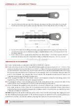
Insert the cable into the open end of the fitting to be swaged, mark the cable where the cable and 
the fitting meet. Remove the cable and check that the mark is at least 84mm from the cable end. 


2.


Re-insert the cable into the fitting to distance previously marked. Start swaging the fitting from the 
closed end as shown above. Continue to swage as indicated above 5 times, first swage is 6mm from 
the depth indicator. 

3.


Ensure that you can no longer see the mark that was made in Step 1. Check the crimped sections are 
within the allowable tolerances using Vemier Callipers. (Allowable tolerances = 11.10 + - 0.2mm). 


IMPORTANT NOTES TO REMEMBER 


Ensure marked cable as indicated in step one is a minimum of 84mm. 


Ensure  all  crimped  sections  (flat)  are  with  11.10mm,  with  a  tolerance  level  of  +  or  -  0.2mm.  This 
distance should be the case of all 8mm 7 x 19 and 7 x 7 cable. The measurement should be taken with 
Vernier Callipers to ensure accuracy. If your measurements are outside the acceptable tolerance range 
this can be a sign of either a loss of pressure in your swaging tool or an indication that your dies are 
worn  or  incompatible.  Any  swaging  that  occurs  outside  the  acceptable  tolerances  will  need  to  be 
restarted using the appropriately amended tools. 


When swaging the cable the mark made in step 1 will disappear during the final swage due to the 
lengthening of the material during the swaging operation. 


The swaged end has a mark indicating the end of the solid section of the  unit and the start of the 
hollow section. Start swaging 6mm from the mark indicating the solid section. 


When completed the swaged section should be a minimum of 80mm long. The dies are made with a 
9mm wide section to crimp. These 9mm crimping sections need to completed 5 times, that is there 
will be five flat sections along the swaged end. In between each crimped section you need to maintain 
a distance of between 5 and 6mm. 

DO NOT 

swage the solid section indicated by the mark on the unit this will damage the swaging tool and 

the dies. (Marking the swaging depth on the end to be swaged unit (84mm from the opening will help to 
avoid this). To do this, use Vernier Callipers, checking the maximum size and minimum size. 


Summary of Contents for EPB-4201

Page 1: ...All products must be installed in accordance with SafetyLink s installation handbook using only products supplied by SafetyLink Pty Ltd Failure to follow all warnings and instructions may result in a...

Page 2: ...G 9 CRIMPING TOOL 18V BATTERY CHARGER SET 10 HOW TO OPERATE USE CH 07 CHARGER 10 CRIMPING TOOL 18V BATTERY CHARGER SET 11 ABOUT THE 18V LI ION BATTERY B 04 B 06 11 CRIMPING TOOL 18V BATTERY CHARGER SE...

Page 3: ...replacement for a period of 1 one year from the date of shipment This limited warranty applies provided that a defects have arisen solely from faulty materials or workmanship b the Products have not r...

Page 4: ...TOOL SPECIFICATION SPECIFICATION DIE NO MODEL NO EPB 4201 NC3035 CU35 OUTPUT 12 TONS NC3050 CU50 VOLTAGE DC 18V NC3070 CU70 WEIGHT 7 3 KGS NC3095 CU95 DIMENSION 460mm L 70mm W 240mm C NC30120 CU120 NC...

Page 5: ...ping material Check your crimping material is suitable for this tool and your crimping material is in the range of EPB SERIES TOOLS Do not crimp without any material in crimping area otherwise the too...

Page 6: ...the battery to CRIMPER as below picture 1 Battery will be buckled to the tool Picture 1 Set battery Follow four steps as below picture 2 to insert the dies 1 Pull out Fixed Ring and put the dies in 2...

Page 7: ...v_Handbook Page 7 of 16 Doc ID MKT 567 Version 2 0 CRIMPING TOOL OPERATING USE After setting the dies crimping material and battery please press the Switch and Oil Return to operate the crimping dies...

Page 8: ...N SITUATION PROBLEM METHOD TO SOLVE NORMAL MOTOR BUT BLADE NOT MOVING OIL IS NOT ENOUGH ADD OIL OR SEND BACK AIR IN OIL RESERVOIR SEND BACK FOR SUPPORT OIL RETURN IS DEFECT SEND BACK FOR SUPPORT NORMA...

Page 9: ...uzzer buzzes once every second it indicates the battery has error defect If the temperature of the battery is high the digital monitor shows The Buzzer buzzes once a second wait until the battery is c...

Page 10: ...E 18V LI ION BATTERY B 04 B 06 B 04 3 0Ah B 06 1 5Ah SPECIFICATION MODEL NO B 04 VOLTAGE 18V WEIGHT 0 6 KG DIMENSION 122mm L x75mm W x69mm H CHARGING TIME 60 70 MINUTES CAPACITY 3 0Ah MEMORY EFFECT NO...

Page 11: ...d its use time will be shorter This is normal Please follow the instructions of battery manual to charge the battery Do not charge the battery directly under the sun or in a space with high temperatur...

Page 12: ...current height safety qualifications SAFETYLINK HEIGHT SAFETY SYSTEMS MUST ONLY BE INSTALLED AS PER OUR INSTALLATION GUIDES TO STRUCTURES AS SPECIFIED IN THE INSTALLATION MANUAL FOR EACH PRODUCT SHOU...

Page 13: ...If your measurements are outside the acceptable tolerance range this can be a sign of either a loss of pressure in your swaging tool or an indication that your dies are worn or incompatible Any swagi...

Page 14: ...Return to Table of Contents Ref Crimping_Tool_18v_Handbook Page 14 of 16 Doc ID MKT 567 Version 2 0 NOTES...

Page 15: ...Return to Table of Contents Ref Crimping_Tool_18v_Handbook Page 15 of 16 Doc ID MKT 567 Version 2 0 NOTES...

Page 16: ...possible IN ACCORDANCE WITH AS NZS 1891 4 2009 CLAUSE 9 5 EQUIPMENT WHICH HAS ARRESTED A FALL OR SHOWS A DEFECT Any piece of equipment including both personal and permanently installed items which ha...

Reviews: