background image

User Setup

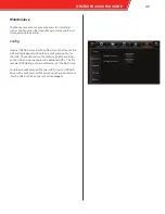
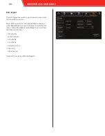
The User Setup menu allows you to set up different users 

who must log in to operate the HVR.  Each user is assigned a 

name, group, and password.

To add a user:

1. 

Tap the Add button.

The Add screen appears.

2. 

Enter a unique alphanumeric user name.

3. 

Select the Admin or Normal User user group.

Admin users have full access to the HVR’s features.  Normal 

users are restricted from accessing the Setup menus.

4. 

Enter a unique alphanumeric password.

5. 

Retype the password in the Confirm password field.

6. 

Tap Save.

The user appears in the User Setup menu list.

• 

Idle Time: select the number of minutes after no activity 

that the user is automatically logged out; select 

Never 

to 

keep users logged in indefinately

• 

Delete: select any number of users and tap the Delete 

button to delete them from the HVR

• 

Edit: select a user and tap the Edit button to change a 

user’s name, user group, or password

After making any entries, tap 

Save

 at the bottom of the screen.

24

OBSERVER 4120 USER GUIDE

Summary of Contents for OBSERVER 4120

Page 1: ...OBSERVER 4120 USER GUIDE...

Page 2: ...ed warranties of merchantability and fitness for a particular purpose Safety Vision shall not be liable for errors contained herein or for incidental or consequential damages in connection with the fu...

Page 3: ...rch 11 System 14 Version Info 14 Modules 15 Server Status 16 Environment 17 Storage 18 Log Search 19 Setup 21 Register Info 21 Time Setup 22 Startup 23 User Setup 24 Network 25 Application 27 Live Vie...

Page 4: ...ol bus Sensor 7 Amber Warning Lights school bus Sensor 6 Door or wheel chair lift Sensor 5 Head Lights Sensor 4 Event Button Sensor 3 Brake Lights Sensor 2 Left Turn Signal Sensor 1 Right Turn Signal...

Page 5: ...this page intentionally left blank 3 OBSERVER 4120 USER GUIDE 3...

Page 6: ...teners Ensure that the front panel of the HVR remains accessible there is a minimum 2 5 inches of clearance for cables and there is adequate space to provide air for the cooling fan Do not install the...

Page 7: ...down or backwards Ensure the SD card s write protection slider is in the unlocked position 1 Open the SD card slot door from the left edge 2 Insert an SD card into the SD card slot label side up with...

Page 8: ...onfiguration menus 4 USB Port Insert a USB flash drive to download events quickly without having to remove the SD card or hard drive can also upload firmware updates and configuration files 5 SD Card...

Page 9: ...ck up data box 5 LAN 1 Port RJ45 Connection for optional network accessories 6 LAN 2 Port RJ45 Connection for the POE Smart Switch IP camera hub The Smart Switch MUST be connected to the LAN 2 port 7...

Page 10: ...rn to the previous menu The SV CP4 HYB monitor incorporates the functionality of a remote control Buttons on the monitor are functionally the same as the remote control buttons described on the next p...

Page 11: ...eys can be used to rewind or fast forward Press the Enter key while viewing the live view to display a comprehensive status screen 4 Additional Remote Control Keys VGA Switch the output mode of the ex...

Page 12: ...name admin and Password admin Home Screen Once logged in the Home Screen displays The Home Screen provides access to the following features REC Recording Search Search for a playback previously record...

Page 13: ...t a day on the calendar and tap the Next button to advance to the channel selection screen Channels Select specific channels you want to review by checking its box You can use the Video Type field to...

Page 14: ...c time can be entered in the field in the upper right Tap on it to make a keypad appear Tap the speaker icon in the upper left of the screen to mute or unmute any audio playback Tap the left and right...

Page 15: ...6 Tap the End time button The Export prompt appears displaying the exported video clips length and file size as well as the capacity of the inserted USB flash drive 7 Select the exported file format...

Page 16: ...t side of the screen to navigate be tween different menus Version Info The Version Info menu provides information on the firmware versions of the HVR in addition to other information Device name uniqu...

Page 17: ...internal Wi Fi module External WIFI status displays the status of a connected external Wi Fi device ESSID ESSID of a connected external Wi Fi device IP address IP address of a connected external Wi Fi...

Page 18: ...which the HVR is con nected Server status connection status Network type type of network used to communicate with the OMS server Protocol type type of protocol used when communicating with the OMS ser...

Page 19: ...in volts the HVR is currently receiving Device temperature displays the internal temperature of the HVR displayed in degrees Celsius HDD heater status displays if the internal HDD heater is currently...

Page 20: ...ype of storage device Status displays if the device is currently Recording is Normal or a problem has occured Free Total displays the ratio of available storage space to the amount of total sotrage sp...

Page 21: ...search In the Log type field select the type of log to search for Alarm log log of of different types of alarms After selecting this option the Alarm type field appears All all alarms IO alarm alarms...

Page 22: ...lm icon next to alarm log entries to automatically begin playback of the alarm Exporting Log Files Tapping the Export button on the lower right begins the export process The selected video can be down...

Page 23: ...gs such as the date time users and start up and shutdown param eters Register Info Device Info OMS ID unique numeric ID assigned to the HVR for identification in the Observer Management System OMS thi...

Page 24: ...l Center Server select this option to automatically syncronize the date and time to an OMS server when the HVR connects NTP sync select this option to automatically syncronize the date and time to an...

Page 25: ...ode Monitor mode select Automatic power up to turn the SV CP4 HYB monitor on automatically with the HVR select Auto standby to leave the monitor in standby mode must be touched to activate when the HV...

Page 26: ...ing the Setup menus 4 Enter a unique alphanumeric password 5 Retype the password in the Confirm password field 6 Tap Save The user appears in the User Setup menu list Idle Time select the number of mi...

Page 27: ...ic subnet mask for the HVR Gateway enter a static network gateway for the HVR Auto get DNS select this option to allow the HVR to receive DNS information automatically Use following DNS select this op...

Page 28: ...ay Server Select a central server to configure from the drop down menu Multiple servers configurations can be saved to add a new server tap the Add button To activate a server select the ON option and...

Page 29: ...ient option which allows you to log into the HVR as an FTP server with an exter nal PC Enter the following information about the FTP client Server Port User Name Password After making any entries tap...

Page 30: ...een select the format of the Live View that appears automatically when the HVR starts up Channel select which channels appear in the Live View Auto Loop The Auto Loop tab allows you to program the Liv...

Page 31: ...n OMS server Transmit Mode select Best fluency Normal fluency Recommended Normal clean or Best clean to adjust the transmission when troubleshooting OMS setups Live OSD Select which pieces of metadata...

Page 32: ...t between 1 and 8 1 being the best for continuously recorded video quality Record mode select Power up continuous recording begins when HVR is powered on Timer HVR records during the configured time s...

Page 33: ...he Setup button next to the Record mode field after selecting Sub Record to display the Setup screen to config ure each individual channel to be displayed in the Live View of OMS Channel Enable Audio...

Page 34: ...the Setup icon for each network The Network Setup screen appears 5 Enter the following for each network Channel Protocol type IP address Port User name Password 41H series cameras leave the User name...

Page 35: ...the I O hub There are four I O hub connections RS232 1 RS232 2 RS485 1 and RS485 2 For each connection select which device is connected None Control panel GPS Data CAN 3Axis Acc and the frequency The...

Page 36: ...taken during alarms or manually Tap the Setup button under each option to configure each channel Snapshot Setup screen Select a channel in the Channel field and configure the fol lowing for each Snap...

Page 37: ...nable panel alarms An alarm is triggered when the panic button on the SV CP4 HYB moni tor or LED panic button panel is pressed Tap the Setup but ton under Trigger and enter the amount of time between...

Page 38: ...and 255 seconds between when the alarm is triggered and when the IO signal is sent Alarm Upload select this option to upload the alarm Linkage screen select a screen to appear on the monitor while the...

Page 39: ...d tap Export to download a configuration file for the HVR The configuration file contains all of the settings on the HVR and can be copied to additional HVRs The file saved as DVRcfg cfg on the root d...

Page 40: ...cted data available or select Export time to request only data in a specific time range Enter a Start time and End time then select from the following file types GPS data file Vehicle info file ACC in...

Page 41: ...from Safety Vision techni cal support and save it to the root directory of a USB flash drive Ensure it is the only file on the flash drive Insert the flash drive into the USB port on the front of the...

Page 42: ...t storage devices con nected to the HVR and displays the ratio of free to total space available for each To format a device tap Format Formatting a device erases all data including recorded video Use...

Page 43: ...menu allows you to reset the HVR s entire config uration to the factory default settings To reset all settings tap the Default button Resetting an HVR erases all settings Use with caution OBSERVER 412...

Page 44: ...cable 3 Ensure the HVR is receiving power and has started up 4 Set a sequential static IP address for the LAN connection connected to the HVR For example if the HVR s IP address is 192 168 1 100 set...

Page 45: ...segments you want to export 3 Click the Backup button The Backup window appears 4 Select one of the following options Synthetic data video can only be played back using the Observer Management System...

Page 46: ...vice erases all data including recorded video Use with caution Log The Log tab provides the same functionality at the Log Search feature on an external monitor Enter the Log type Operate type and the...

Page 47: ...iguration duplicates the Setup menus accessed with an external monitor Navigate through the different menus using the tabs on the left of the screen Remember to click Save after changing any parameter...

Page 48: ...equired Embedded module 802 11b g n GPS Antenna Included Embedded module location tracking speed detection and sync time Interfaces 2 RS232 2 RS485 2 USB 2 0 Acelerometer 3 Axis Sensors 8 inputs 2 out...

Page 49: ...Appendix B Dimensions 47 OBSERVER 4120 USER GUIDE...

Page 50: ...this page intentionally left blank 48 OBSERVER 4120 USER GUIDE...

Page 51: ...10 days of discovering the defective product or part and provide a description of the defect and complete information about the manner of its discovery All warranty servicing of this product must be p...

Page 52: ...opyright 2015 Safety Vision LLC All Rights Reserved CORPORATE HEADQUARTERS 6100 W Sam Houston Pkwy N Houston TX 77041 5113 Main 713 896 6600 Toll Free 800 880 8855 Fax 713 896 6640 www safetyvision co...

Reviews: