background image

Powered by Safety

®

15

Equipment Description

01.4IB.77020

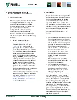
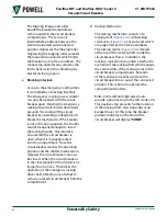
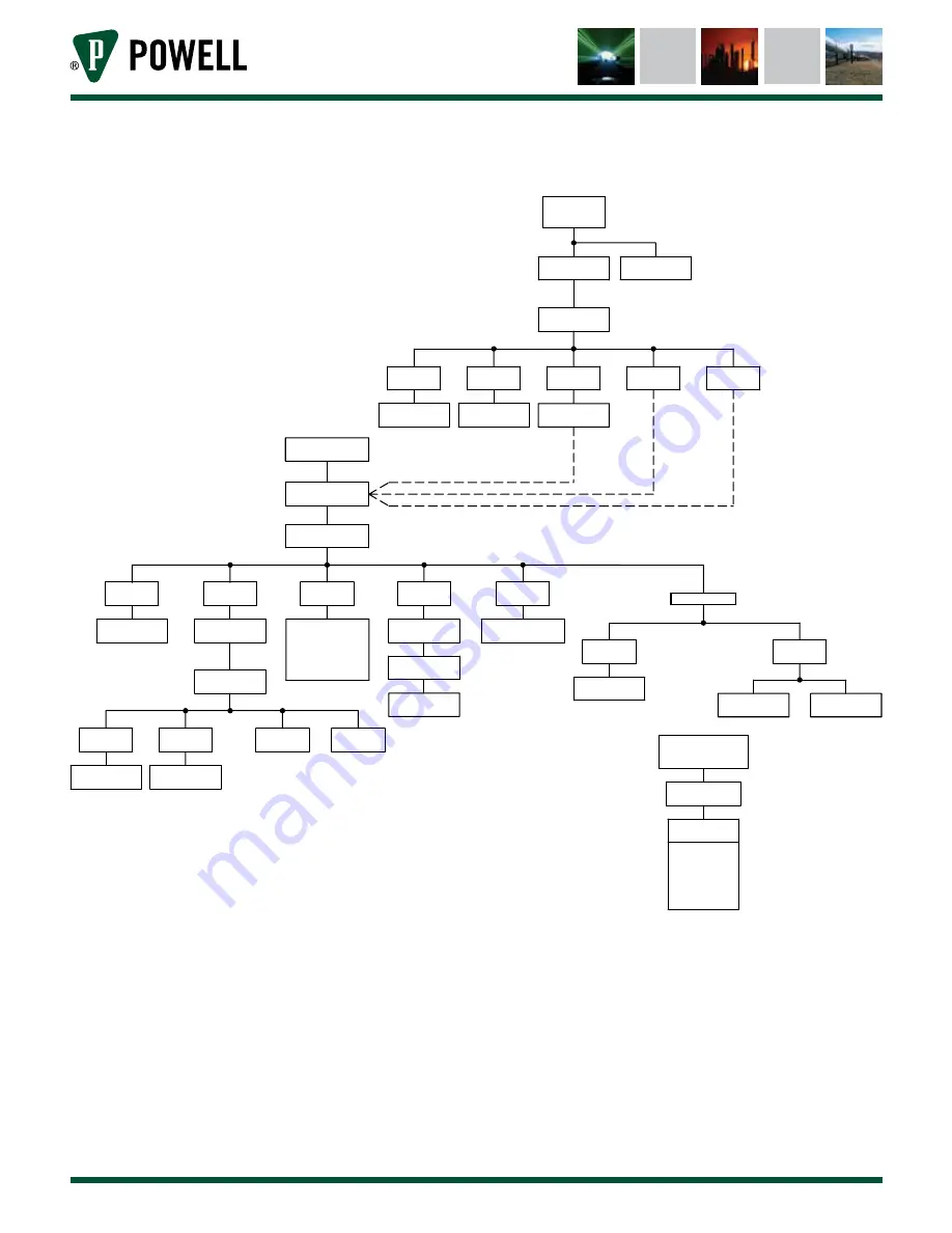
Figure 7 

Operation Sequence

 SECONDARY
DISCONNECT
      MAKES

CLOSE SPRING

CHARGED

BREAKS

LS 

MAKES

LCS

ENERGIZED

GREEN LIGHT

WHITE LIGHT

ENERGIZED

"Y" CIRCUIT

DISABLED

"CS/C" MAKES

CLOSE CONTROL

CLOSE COIL "CC"

ENERGIZED

DISCHARGED

CLOSE SPRING

MOTOR "M"

ENERGIZED

DE-ENERGIZED

WHITE LIGHT

LS 

MAKES

BREAKS

LS 

LS 

MAKES

BREAKS

LS 

PREVENTS

CLOSE COIL

MOTOR "M"

DE-ENERGIZED

ENERGIZED

WHITE LIGHT

LS 

BREAKS

MAKES

LS 

CHARGED

CLOSE SPRING

VCB CLOSED

BREAKS

52/b

"Y" COIL

ENERGIZED

DE-ENERGIZED

CLOSE COIL "CC"

ENERGIZATION

BEFORE

FULLY CHARGED

SPRING IS

RELEASED

SWITCH IS

BEFORE CONTROL

IF VCB TRIPS

PUMPING

PREVENTS

BREAKS

"Y" CONTACT

MAKES

"Y" CONTACT

"Y" COIL

"SEALS IN"

LS 

BREAKS

MAKES

LS 

52/a
MAKES

GREEN LIGHT

DE-ENERGIZED

BREAKS

52/b

ENERGIZED

RED LIGHT

TRIP CIRCUIT

SET UP

CONTROL SWITCH

"CS/C" BREAKS

RELEASE CLOSE

DE-ENERGIZED

"Y" COIL

MAKES

LS 

MOTOR "M"

ENERGIZED

DE-ENERGIZED

MOTOR "M"

BREAKS

LS 

MAKES

LS 

Summary of Contents for POWELL PowlVac-ND 4 Series

Page 1: ...Instruction Bulletin 01 4IB 77020 PowlVac ND and PowlVac NDA Series 4 Vacuum Circuit Breakers 5kV 1200A 2000A 36kA 50kA Powered by Safety ...

Page 2: ...D and PowlVac NDA Series 4 Vacuum Circuit Breakers Powered by Safety Contact Information Powell Electrical Systems Inc powellind com info powellind com Service Division 7232 Airport Blvd Houston Texas 77061 713 944 6900 phone 713 948 4569 fax ...

Page 3: ...sed without the safety alert symbol is used to address practices not related to personal injury CAUTION NOTICE NOTICE is used to address practices not related to personal injury Qualified Person For the purposes of this manual a qualified person as stated in NFPA 70E is one who has skills and knowledge related to the construction and operation of the electrical equipment and installations and has ...

Page 4: ...Powered by Safety 4 01 4IB 77020 PowlVac ND and PowlVac NDA Series 4 Vacuum Circuit Breakers This page is intentionally left blank ...

Page 5: ...rical Description 16 C Racking Mechanism For PowlVac ND Series 4Circuit Breaker 17 1 General Description 17 2 Closed Door Racking Mechanism 19 D Automatic Racking Mechanism For PowlVac NDA Series 4Circuit Breaker 20 1 General Description 20 2 Racking Mechanism 21 E Circuit Breaker Compartment Interfaces 22 1 Primary Disconnecting Devices 22 2 Secondary Disconnecting Devices 22 3 MOC Mechanism Oper...

Page 6: ...cted to the Test Disconnected Position 35 5 Removing the Circuit Breaker from the Test Disconnected Position out of the Circuit Breaker Compartment 36 6 Remote Racking 36 F Racking Procedures for PowlVac NDA Series 4Circuit Breaker 37 1 Prior to Inserting the Circuit Breaker into the Circuit Breaker Compartment 37 2 Inserting the Circuit Breaker to the Test Disconnected Position 38 3 Inserting the...

Page 7: ...3 Primary Resistance Check 57 Ch 6 Recommended Renewal Parts and Replacement Procedures 58 A Ordering Instructions 58 B Recommended Renewal Parts 58 C Replacement Procedures 58 1 Vacuum Interrupter Assembly 59 2 Closing Coil Assembly 59 3 Primary Shunt Trip Coil Assembly 59 4 Secondary Shunt Trip Coil Assembly 59 5 Undervoltage Device Assembly 59 6 Charging Motor Assembly 59 7 Anti Pump Relay Asse...

Page 8: ... Circuit Breaker on Crane 25 Figure 12 Secondary Disconnect Device 34 Figure 13 Racking Handle Insertion 34 Figure 14 Circuit Breaker Anti Rollout Latch 36 Figure 15 Lubrication 47 Figure 16 Lubrication cont 48 Figure 17 Main Closing Spring Assembly Installed 49 Figure 18 Main Closing Spring Assembly Compressed for Removal 49 Figure 19 Primary Secondary Trip Prop Adjustment 51 Figure 20 Feeler Gau...

Page 9: ...Powered by Safety v 01 4IB 77020 This page is intentionally left blank ...

Page 10: ... servicing maintenance or any act requiring the operator to make physical contact with the equipment the power source must be disconnected and the equipment grounded Failure to do so may result in death or serious injury NOTICE The information in this instruction bulletin is not intended to explain all details or variations of the Powell equipment nor to provide for every possible contingency or h...

Page 11: ...cular type of circuit breaker The illustrations in this document are provided as general information to aid in showing component locations All illustrations and photos are shown using deenergized equipment Follow the appropriate safety precautions while handling any of the equipment Failure to do so may result in death or serious injury WARNING To the extent required the products described herein ...

Page 12: ... type to be used for voltages exceeding 1kV a c or IEC 61243 2 Live Working Voltage Detectors Part 2 Resistive type to be used for voltages of 1kV to 36kV a c or IEC 61243 3 Live Working Voltage Detectors Part 3 Two pole voltage type Ch 2 Safety A Safe Work Condition The information in Section A is quoted from NFPA 70E 2018 Article 120 120 5 Establishing an Electrically Safe Work Condition 120 5 P...

Page 13: ...Power Lines and Equipment is an example of a standard that contains information on capacity of temporary protective grounding equipment c Impedance Temporary protective grounding equipment and connections shall have an impedance low enough to cause immediate operation of protective devices in case of unintentional energizing of the electric conductors or circuit parts B Safety Guidelines Study thi...

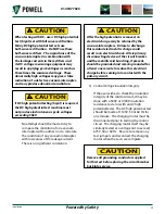
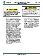
Page 14: ...e it from the metal clad switchgear 2 DO NOT WORK ON A CIRCUIT BREAKER WITH THE CONTROL CIRCUIT ENERGIZED 3 EXTREME CARE MUST BE EXERCISED TO KEEP ALL PERSONNEL TOOLS AND OTHER OBJECTS CLEAR OF MECHANISMS WHICH ARE TO BE OPERATED DISCHARGED OR RELEASED These circuit breakers utilize stored energy mechanisms These mechanisms must be serviced only by skilled and knowledgeable personnel capable of re...

Page 15: ... of steel used in the frame and front cover construction are between the test personnel and the vacuum interrupters and that the test personnel be no closer than one meter 3 from the front of the circuit breaker THE CIRCUIT BREAKER SHALL BE EITHER FULLY OPEN OR FULLY CLOSED WHEN MAKING HIGH POTENTIAL TESTS DO NOT TEST WITH CONTACTS PARTIALLY OPEN F Safety Labels The equipment described in this doc...

Page 16: ... contact assemblies through operating pushrods Figure 3 al In the same metal enclosed compartment as the stored energy mechanism is the circuit breaker racking mechanism and interlocks which control the movement of the circuit breaker between the test disconnected and connected positions The racking mechanism provides the motion to engage disengage the primary disconnecting devices and to open clo...

Page 17: ...tch the ratchet wheel after each advance from the drive pawl To ensure correct synchronization of the drive and holding pawl the position of the holding pawl support arms are adjustable by the holding pawl adjusting eccentric Figure 4 t located at the left front of the mechanism When the mechanism is operated manually the top pawl becomes the drive pawl and the bottom pawl becomes the holding pawl...

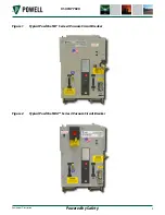
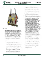
Page 18: ...Powered by Safety 9 Equipment Description 01 4IB 77020 Figure 1 Typical PowlVac ND Series 4 Vacuum Circuit Breaker Figure 2 Typical PowlVac NDA Series 4 Vacuum Circuit Breaker ...

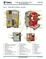
Page 19: ...al Close Operator m Secondary Disconnect Receptacle n Operations Counter o Spring Charge Indicator p Anti Rollout Latch q MOC Actuator r Standoff Insulator s Vacuum Interrupter Support t TOC Actuator u Upper Primary Disconnecting Device v Vacuum Interrupter w Lower Primary Disconnecting Device x Frame y Ground Connection z Serial Number Plate Location aa Wheel ab Crank Arm Roller ac Racking Shaft ...

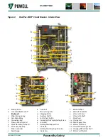
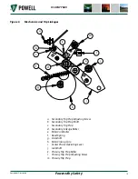
Page 20: ...in Cam Roller j Reset Spring k Camshaft l Main Closing Cam m Charging Motor n Auxiliary Switch o Latch Check Switch p Secondary Trip Prop Adjusting Screw q Jackshaft r Holding Pawl Support Arm s Crank Pin t Holding Pawl Adjusting Eccentric u Crank Arm v Ratchet Wheel w Pawl Lift Drive Plate x Close Latch Arm y Close Latch Shaft z Drive Pawl aa Closing Coil ab Pawl Support Arm ac Motor Cutoff Cam a...

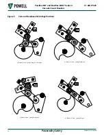
Page 21: ...7020 PowlVac ND and PowlVac NDA Series 4 Vacuum Circuit Breakers Figure 5 Cam and Fundamental Linkage Positions a Breaker Open Spring Charged Links Reset b Breaker Closed Spring Discharged c Breaker Open Spring Discharged d Breaker Closed Spring Charged ...

Page 22: ...Prop Adjusting Screw b Secondary Trip Prop Shaft c Secondary Trip Prop d Secondary Linkage Roller e Main Cam Roller f Reset Spring g Camshaft h Main Closing Cam i Center Phase Operating Lever j Jackshaft k Primary Trip Prop Roller l Primary Trip Prop Adjusting Screw m Primary Trip Prop l c b d e f g h i j k a m ...

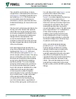
Page 23: ...re preloaded to a value sufficient to resist vacuum interrupter contact separation under the highest electromagnetic forces exerted by the rated short circuit current Further movement of the operating pushrod assembly compresses the contact loading spring even more and produces a gap between the face of the spring yoke and the lock nut For each phase bell cranks Figure 3 ag are located on the outs...

Page 24: ...S LS PREVENTS CLOSE COIL MOTOR M DE ENERGIZED ENERGIZED WHITE LIGHT LS BREAKS MAKES LS CHARGED CLOSE SPRING VCB CLOSED BREAKS 52 b Y COIL ENERGIZED DE ENERGIZED CLOSE COIL CC ENERGIZATION BEFORE FULLY CHARGED SPRING IS RELEASED SWITCH IS BEFORE CONTROL IF VCB TRIPS PUMPING PREVENTS BREAKS Y CONTACT MAKES Y CONTACT Y COIL SEALS IN LS BREAKS MAKES LS 52 a MAKES GREEN LIGHT DE ENERGIZED BREAKS 52 b E...
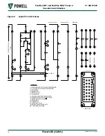
Page 25: ...OWNW SPRING DISCHARGED LCS LATCH CHECK SWITCH SHOWNW SPRING DISCHARGED DEVICE IDs Y ANTI PUMP RELAY TC BREAKERTRIP COIL CC BREAKER CLOSE COIL M CHARGING MOTOR 52 a BREAKER AUXILIARY CONTACT NORMALLY OPEN 52 b BREAKER AUXILIARY CONTACT NORMALLY CLOSED SD BREAKER SECONDARY DISCONNECT TB TERMINAL BLOCK TRIP1 CLOSE RM RACKING MOTOR TO RATED CONTROL POWER TYPICAL UV UNDERVOLTAGETRIP COIL TRIP2 COMM FUT...

Page 26: ... can fall into the reset position The reset spring stretches between an extension of the main cam roller pin and a spring support pin located on the left mechanism side sheet The latch check switch Figure 4 o operated by a lever on the trip shaft will close as the secondary trip prop reaches the fully reset position 2 Electrical Description a Charging Motor The function of the charging motor Figur...

Page 27: ...l schemes is shown in Figure 7 Circuit breaker mounted auxiliary contacts not used in the control circuit are brought out for control and indication functions The metal clad switchgear equipment may provide a circuit breaker MOC Mechanism Operated Cell Switch for additional contacts C Racking Mechanism For PowlVac ND Series 4 Circuit Breaker 1 General Description The racking mechanism is the mecha...

Page 28: ...ment with the circuit breaker closed or with the main closing spring charged Closed Door Racking CDR circuit breaker interlocking is primarily achieved by means of an interlock bar acting upon the racking drive shaft extension an interlock bar attached to the secondary disconnect receptacle and a tripping linkage and roller on the right side of the frame of the circuit breaker that interfaces with...

Page 29: ...ng is discharged prior to removal from the compartment 2 Closed Door Racking Mechanism The closed door racking mechanism consists of a racking shaft Figure 9 c with racking crank arms Figure 3 ad at each end which are supported by the frame side sheets The racking shaft also supports a worm gear assembly Figure 9 b at the right end just inside the right side sheet In addition the racking crank arm...

Page 30: ...ac NDA Series 4 Circuit Breaker for more information b Interlocking PowlVac circuit breakers are provided with several interlocks that operate in conjunction with the circuit breaker compartment to ensure the proper operation of the circuit breaker Do not attempt to modify or bypass these interlocks as they are necessary for the safe operation of the circuit breaker The purpose of the interlocks i...

Page 31: ... racked into the compartment Once the circuit breaker reaches the operating position and the shutter mechanism is released the circuit breaker can now be closed When the circuit breaker is in the closed position the shutter is no longer free to move This blocks the operation of the emergency racking drive shaft deterring any attempt to remove a closed circuit breaker from the compartment 2 Racking...

Page 32: ... positions of the circuit breaker 3 MOC Mechanism Operated Cell Switch Actuator The MOC located in the switchgear is operated by a plunger which extends from the circuit breaker operating mechanism Movement of the MOC actuator Figure 3 q is directly related to the movement of the circuit breaker mechanism and contacts 4 TOC Truck Operated Cell Switch Actuator The TOC located in the switchgear is o...

Page 33: ...led vacuum interrupters to control the primary circuit Some vacuum interrupters appear to be identical in size and shape externally but types vary in ratings due to the differences in their internal construction For a listing of the vacuum interrupters used in PowlVac ND Series 4 and PowlVac NDA Series 4 circuit breakers see Table E Primary Current Path VACUUM INTERRUPTERS MUST BE REPLACED ONLY WI...

Page 34: ... equipment In these cases the circuit breaker will be in the test disconnected position and it will be bolted to the compartment floor by use of a shipping bracket The horizontal leg of the bracket is bolted to the compartment floor and the vertical leg is bolted to the front of the circuit breaker using the lower cover bolts Remove these four bolts discard the shipping angle and replace the four ...

Page 35: ... be stored in such a manner as to leave all doors and panels accessible for inspection The equipment must be inspected on a routine basis to assure operational integrity 2 Equipment designed for outdoor exposure may be stored either in indoor or outdoor storage locations The equipment must be protected from airborne external contaminates if stored outdoors Outdoor storage will also require additio...

Page 36: ...ential test described below is strongly recommended DC testing is not the preferred method however values are provided due to the availability of DC test sets CAUTION If DC high potential is performed the DC high potential test machine must NOT produce instantaneous peak voltages exceeding 20kV The circuit breaker insulation should be tested with the circuit breaker vacuum interrupter contacts in ...

Page 37: ...ge insulation integrity See Ch 4 Installation D Placing the Circuit Breaker Into Service 1 High Voltage Insulation Integrity Powell offers a compact and lightweight PowlVac Vacuum Integrity Tester designed specifically for PowlVac circuit breakers If this device is used refer to the instruction bulletin provided with the vacuum integrity tester Powell recognizes the widespread use of DC hipot equi...

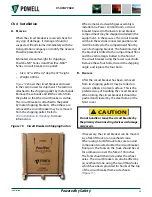
Page 38: ...significant correlation After the high potential is removed an electrical charge may be retained by the vacuum interrupters Failure to discharge this residual electrostatic charge could result in an electrical shock All six primary disconnecting devices of the circuit breaker and the metallic mid band ring if present should be grounded and remain grounded for at least one minute to reduce this ele...

Page 39: ...inserting the manual charging handle into the manual charging crank and pushing down until a metallic click is heard this indicates that the holding pawl has dropped into place on the ratchet wheel Lift the handle until it is horizontal and then depress The procedure is repeated until the spring charge indicator indicates CLOSING SPRING CHARGED This requires about 60 operations of the handle Once ...

Page 40: ...uitry of the circuit breaker compartment Caution must be exercised if this option is chosen to ensure that operation of the control circuitry of the compartment used for test does not cause undesirable effects or unintended operation of other interconnected equipment such as supervisory controls SCADA or automatic transfer schemes First remove the control fuses in the compartment Connect the jumpe...

Page 41: ...e main barrier assembly has been properly fastened in place Failure to do so may cause equipment damage and or minor or moderate injury CAUTION E Racking Procedures for PowlVac ND Series 4 Circuit Breaker Refer to the metal clad switchgear instruction bulletin and drawings produced specifically for the installed equipment including additional information and cautions before attempting to insert th...

Page 42: ...it breaker rating meets or exceeds the metal clad switchgear rating CAUTION Before inserting a circuit breaker into the circuit breaker compartment be sure that the indicator flag on the front cover of the circuit breaker displays TEST CAUTION b Racking the Circuit Breaker into the Circuit Breaker Compartment The described racking procedures apply only for the PowlVac ND Series 4 circuit breakers ...

Page 43: ...acking procedure review Chapter 2 NOTICE 2 Inserting the Circuit Breaker to the Test Disconnected Position To insert the circuit breaker into the upper compartment a lifting device must be used Refer to the Lifting Device instruction bulletin for details on how to insert a circuit breaker into the upper compartment NOTICE Prior to inserting the circuit breaker into the circuit breaker compartment ...

Page 44: ...he plug is fully inserted move the secondary disconnect latch Figure 12 a from left to right until it has engaged the housing of the secondary disconnect plug Figure 12 Secondary Disconnect Device a b d c a Secondary Disconnect Latch b Secondary Disconnect Receptacle c Secondary Disconnect Plug d Interlock Bar Note This is the Test Position The anti rollout latch on the lower right side of the cir...

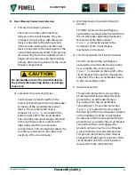
Page 45: ...ker reaches the end of the racking travel the operator will notice an increased amount of force If the user continues to apply force a torque limiter on the racking handle will produce an audible clicking sound indicating the torque limit is reached at 35 ft lb Should the operator continue to apply force the torque limiter will continue to operate with no further buildup of torque on the circuit b...

Page 46: ...hdrawing the circuit breaker Removal of the secondary disconnect plug will trip a closed breaker and discharge the main closing spring CAUTION c Press the anti rollout latch downward to release the circuit breaker and pull the circuit breaker out of the circuit breaker compartment Figure 14 a Figure 14 Circuit Breaker Anti Rollout Latch a a Anti Rollout Latch 6 Remote Racking This is an alternativ...

Page 47: ...other and deter further insertion The interference will occur before the circuit breaker reaches the disconnected position Do not attempt to force the circuit breaker past the compartment interference plate or remove the interference plates from either the compartment or the circuit breaker Remove the incorrectly rated circuit breaker and insert a properly rated circuit breaker into the circuit br...

Page 48: ...rify that the circuit breaker rating meets or exceeds the metal clad switchgear rating CAUTION Before inserting a circuit breaker into the circuit breaker compartment be sure that the indicator flag on the front cover of the circuit breaker displays TEST CAUTION Before attempting to rack a circuit breaker in or out of a circuit breaker compartment equipped with a key interlock make sure that the i...

Page 49: ...disconnect plug Note This is the Test Position The anti rollout latch on the lower right side of the circuit breaker will engage the block in the compartment preventing accidental removal of the circuit breaker from the compartment 3 Inserting the Circuit Breaker to the Connected Position The preferred method of racking the NDA circuit breaker is electrically from a remote location via Sentry remo...

Page 50: ...ary disconnecting devices Continue racking until the breaker position indicator displays CONN When the circuit breaker reaches the end of the racking travel the user will notice an increased amount of force If the operator continues to apply force a torque limiter on the racking handle will produce a sharp clicking sound indicating the torque limit is reached at 35 ft lb Should the operator contin...

Page 51: ...4 a to release the circuit breaker and pull the circuit breaker out of the circuit breaker compartment 6 Emergency Racking Out Procedure In the event of an emergency such as loss of control power the NDA circuit breaker is equipped with an emergency racking mechanism which enables racking the circuit breaker into or out of the connected position NOTICE Prior to removing the circuit breaker from th...

Page 52: ...r perform the following 1 Push the secondary disconnect latch Figure 12 a to the left This will unlock the secondary disconnect plug allowing it to be removed Remove the secondary disconnect plug Removal of the secondary disconnect plug will trip a closed breaker and discharge the main closing spring CAUTION 2 Press the anti rollout latch Figure 14 a to release the circuit breaker and pull the cir...

Page 53: ...liability and operating environment Any time the circuit breaker is known to have interrupted a fault current at or near its rating it is recommended that the circuit breaker be inspected and the necessary maintenance be performed as soon as practical Some atmospheric conditions such as extremes of dust moisture or corrosive gases might indicate inspection and maintenance at more frequent interval...

Page 54: ...place loose or missing hardware Any damaged parts that will interfere with the normal operation of the circuit breaker should be replaced This inspection will be much easier if the front cover and interphase barriers are removed Clean the circuit breaker by removing any loose dust and dirt Do not use compressed air to clean the circuit breaker This may result in loose dirt or grit being blown into...

Page 55: ...ing the Circuit Breaker Into Service 4 Mechanical Operation Check Ch 4 Installation D Placing the Circuit Breaker Into Service 6 Emergency Racking Mechanism Check PowlVac NDA Series 4 Circuit Breaker Only 2 Lubrication Before applying any type of lubrication to the circuit breaker the stored energy mechanism should be in the OPEN position and all springs discharged CAUTION Powell offers a complete...

Page 56: ... 15 m C Oil Apply to penetrate where pin passes through end link Main Closing Spring Guide Rod Figure 16 n C Oil Racking Mechanism Figure 16 o C Oil A Grease Apply C Oil to the crank arm rollers and racking crank arms Wipe clean Apply A Grease to worm gear Primary Trip Prop Figure 16 p C Oil Open Close Flag Drive Lever Pin at Jackshaft Figure 16 q C Oil Flag Support Pin Figure 16 r C Oil Jackshaft...

Page 57: ...tion b Spring Yoke Pin c Trip Shaft Bearing d Jackshaft Support e Pawl Support Arm f Crank Pin h Motor Drive Shaft Roller Needle Bearings j Close Latch Shaft Face i Pawls m Fundamental Linkage Pin l Jackshaft Lever Pin g Ratchet Wheel a b c d e f g h i j k l m a Primary Disconnecting Device k Secondary Disconnect Receptacle ...

Page 58: ...Flag Drive Lever Pin at Jackshaft r Flag Support Pin s Jackshaft Outer Bearings Support t Ground Connection v Wheel u Motor Drive Shaft Coupling aa Fundamental Linkage z Motor Cutoff Cam y Close Shaft Support Bearing x Camshaft Needle Bearings w Motor Drive Shaft Support Bearings ab Racking Drive Shaft Extension PowlVac ND Only n o ab p q r s t u v w x y z aa ...

Page 59: ...sher Figure 17 2 Remove the horizontal bracket at the top of the main closing spring by unfastening the two attachment bolts Figure 17 c 3 Remove the spacer from above the bracket 4 Turn the bracket 90 and replace it on the top of the spring yoke Figure 18 a 5 Place the spacer below the bracket with the flat washer below it 6 Insert bolt and tighten until the tension is taken off the connecting ro...

Page 60: ...reverse the steps in Ch 5 Maintenance B Mechanism Area 3 Closing Spring Removal Note Even though the mechanism was slow closed when it is opened it will operate at full speed keep all fingers and toes out of the way etc 5 Mechanism Adjustments Several factory adjustments in the stored energy mechanism are described below NO ADJUSTMENT OF THESE SETTINGS IS REQUIRED FOR ROUTINE MAINTENANCE but they ...

Page 61: ...usting Screw e Rivet f Trip Bar Sight Line b c d e f 0 005 0 015 a Perform the following procedures to adjust the primary trip prop 1 Remove the main closing spring Refer to Ch 5 Maintenance B Mechanism Area 3 Closing Spring Removal 2 Adjust the primary trip prop adjusting screw Figure 19 d so that with the fundamental linkage in the reset position the clearance between the primary trip prop rolle...

Page 62: ...ing the manual charge handle per Ch 4 Installation D Placing the Circuit Breaker Into Service 4 Mechanical Operation Check 9 Manually CLOSE the circuit breaker 10 Using leaf type feeler gauges with a total of 0 090 thickness selected position the feeler gauge Figure 20 Figure 20 Feeler Gauge 11 Slowly depress the trip coil armature using the manual charge handle Depress the handle until the armatu...

Page 63: ...mature gap and does trip with 0 030 gauge inserted into the trip coil armature gap 16 Perform the latch check switch adjustment per the procedure found in Ch 5 Maintenance B Mechanism Area 4 Mechanism Adjustments d Latch Check Switch Adjustment 17 Replace circuit breaker front cover d Latch Check Switch Adjustment Figure 21 Latch Check Switch Adjustment b Pivot Screw 0 045 a c a Latch Check Switch...

Page 64: ...CHARGED 8 Reinstall the circuit breaker main closing spring e Adjustment of Close Latch Shaft The close latch shaft Figure 4 y passes through the side sheets of the stored energy mechanism frame at the front of and below the cam shaft The left end of the shaft is shaped to make a latch face and interferes with the close latch arm Figure 4 x which is fixed to the cam shaft The other end of the clos...

Page 65: ... contact block and the vacuum interrupter linkage pins in both the open and closed positions Using calipers measure from the bottom of the lower Current Transfer Block to the top of the Operating Pin Refer to Figures 22 23 Record the value measured Figure 22 Measurement of Open Position a b c a Open Position Gap b Bottom of Current Transfer Block c Top of Operating Pin Measure the distance between...

Page 66: ...g contacts 3 Vacuum Integrity Refer to Ch 4 Installation D Placing the Circuit Breaker Into Service for information on vacuum integrity and testing of vacuum interrupters 4 MechanicalAdjustmentofVacuumInterrupters There are no adjustments required for routine maintenance of a vacuum interrupter assembly There are several factory adjustments which will vary over the operating life of the vacuum int...

Page 67: ...e with the circuit breaker closed Measure the voltage drop across the primary contacts and calculate the resistance The resistance should not exceed the values provided in this instruction bulletin for the specific type and rating of the circuit breaker being measured When making this test be sure the test current passes through both main horizontal primary disconnecting devices of each pair or re...

Page 68: ...y not be identical to the original parts Tables E F and G list the recommended spare parts to be carried in stock by the user The recommended quantity is not specified This must be determined by the user based on the application As a minimum it is recommended that one set of parts be stocked per ten circuit breakers or less Powell recommends that only qualified technicians perform maintenance on t...

Page 69: ...condary Shunt Trip Coil Assembly for replacement and installation procedures 5 Undervoltage Device Assembly Refer to service manual 01 4SM 1801 Undervoltage Device for PowlVac ND for replacement and installation procedures 6 Charging Motor Assembly Refer to service manual 01 4SM 1200 Charging Motor Assembly for replacement and installation procedures 7 Anti Pump Relay Assembly Refer to service man...

Page 70: ...8G01 77017G02 05PV50SNDX 4 4 76 2000 77014G03 77018G01 77017G02 05PV50SNDM 4 4 76 1200 77014G03 77018G01 77017G02 05PV50SNDM 4 4 76 2000 77014G03 77018G01 77017G02 05PV36NDAX 4 4 76 1200 77014G01 77018G01 77017G01 05PV36NDAX 4 4 76 2000 77014G01 77018G01 77017G01 05PV36NDAM 4 4 76 1200 77014G01 77018G01 77017G01 05PV36NDAM 4 4 76 2000 77014G01 77018G01 77017G01 05PV50NDAX 4 4 76 1200 77014G03 7701...

Page 71: ...it breaker if the circuit breaker was originally equipped with this item All circuit breakers have a closing coil primary shunt trip coil charging motor and an anti pump relay assembly Secondary shunt trip coils and undervoltage device assemblies are optional see notes 2 7 2 Primary shunt trip coil is available as a 3 cycle and 5 cycle control device A circuit breaker with an original 5 cycle trip...

Page 72: ...s and Replacement Procedures 01 4IB 77020 Figure 25 Control Devices a b c d e a Primary Shunt Trip Coil 3 cycle b Primary Shunt Trip Coil 5 cycle c Charging Motor Assembly d Closing Coil Assembly e Anti Pump Relay f Undervoltage Device Assembly f ...

Page 73: ...Breakers Table G Miscellaneous Parts Description Catalog Number Illustration Auxiliary Switch Push on Terminals 102112PB Ground Connection 69433G01 Latch Check Switch BA 2RV2 A2 Motor Cutoff Switch Assembly 77034G01 PowlVac Hardware Kit 60500G24 PowlVac Lubrication Powlube 104 Operating Pushrod Assembly 5kV 36kA 77017G01 5kV 50kA 77017G02 ...

Page 74: ...it Breakers May 2018 Powered by Safety Powell Electrical Systems Inc Service Division Houston PO Box 12818 Houston TX 77217 Tel 713 944 6900 Fax 713 948 4569 powellind com info powellind com 2006 Powell Industries Inc All rights reserved 5kV 1200A 2000A 36kA 50kA ...

Reviews: