Powered by Safety
®
17
Equipment Description
01.4IB.77020
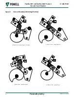
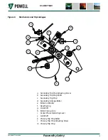
The fundamental linkage is restrained from
movement by the secondary trip prop
acting on the primary trip prop roller. A
component of force tends to make the
primary trip prop rotate upward, but it
is restrained by the secondary trip prop
face acting on the primary trip prop roller.
The clearance between the primary trip
prop roller and the secondary trip prop
is controlled by the primary trip prop
adjusting screw. When the trip shaft is
rotated by the action of the manual trip
operator or the primary shunt trip coil, the
secondary trip prop face moves downward
and permits the primary trip prop to rotate
upward, thus permitting the main linkage
to move upward and the jackshaft to
rotate, opening the circuit breaker. The left
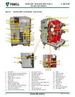
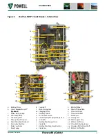
jackshaft levers engage a shock absorber
, which controls the rebound
of the vacuum interrupter contacts on an
opening operation.
With the standard electrical control
scheme, as soon as the main closing spring
is discharged on a closing operation, the
charging motor is switched on to recharge
the springs. This leaves the main closing
cam in a position where a tripped linkage
can reset under the action of the reset
spring
and the primary and
secondary trip props can fall into the
reset position. The reset spring stretches
between an extension of the main cam
roller pin and a spring support pin located
on the left mechanism side sheet. The
latch check switch
, operated
by a lever on the trip shaft, will close as the
secondary trip prop reaches the fully reset
position.
2) Electrical Description
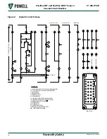
a. Charging Motor
The function of the charging motor
is to compress the main
closing spring of the stored energy
mechanism, thus providing the
necessary energy to close the circuit
breaker. The charging motor, located
at the bottom right of the base pan, is
assembled to the circuit breaker by a
cover plate that is bolted to the circuit
breaker frame right side sheet.
b. Motor Cutoff Switch
The motor cutoff switch
provides an electrical break in the
control circuit supplying the charging
motor when the main closing spring
is fully charged and the stored energy
mechanism is ready for a closing
operation. It is located at the bottom
right of the mechanism, and is
supported by a bracket which is bolted
to the circuit breaker base pan.
c. Anti-Pump Relay
The anti-pump relay
provides a logic function for the control
circuit which prevents a continuous
electrical close signal from causing the
circuit breaker to continuously re-close
after a trip signal. The anti-pump relay
is located on the circuit breaker frame,
inside the circuit breaker left frame side
sheet, and is supported by two screws.


