background image


c.


SECURE WORK PROPERLY. If a piece is supported on both sides of the cut in such a way that it allows 
the material to bow and pinch the blade, it may produce kickback.  Do not cut pieces smaller than the 
saw carriage.  Support large panels properly. 

d.


IF THE BLADE BINDS, TURN SAW OFF!  The saw or work piece may kick back.  Keep hands, body, 
and bystanders out of the path of the blade and material. 

e.


STAY ALERT.  Watch what you are doing and use common sense.  Do not allow yourself to be 
distracted.  Do not operate the tool when you are tired or under the influence of drugs or alcohol. Hold 
the tool and material firmly and exercise control at all times.  Position yourself and co-workers out of the 
kickback path.  Repetitive cuts that lull you into careless movements can also cause kickback.  A brief 
“stretch” may be all that is necessary to avoid a problem. 

f.


RESTARTING IN MID-CUT.  If the saw is stopped in mid-cut, TURN SAW OFF!   Allow the blade to 
stop.  Then back up the saw (if crosscutting) or the board (if rip cutting) before restarting. 

g.


IF THE BLADE STALLS, TURN SAW OFF!  DO NOT TURN THE SWITCH ON AND OFF.  A dull blade 
or excess pressure may cause stalling.  TURN OFF the switch immediately if the blade binds or the saw 
stalls, and remove the saw from the cut. 

h.


AVOID CUTTING NAILS OR OTHER FASTENERS.  Inspect for and remove all metal fasteners before 
cutting. 

i.


SUPPORT THIN MATERIAL.  Large sheets such as paneling, Formica, etc., tend to warp or sag and 
must be well supported over their entire length to avoid pinching the blade.  Optional hold down bar 
recommended for this application.   

27.


HANDLE THE COUNTERBALANCE WITH CARE.  The counterbalance cable is under tension.  See page 16. 
Always attach the cable to the saw carriage before removing the cable clip.  Do not pull on the cable by hand 
or  attempt  to  disassemble  or  repair  the  counterbalance.    Replacement  counterbalances  can  be  purchased 
directly from Safety Speed, or an authorized dealer.  


28.


DO NOT USE PUSH STICKS. 

29.


CROSSCUTTING (VERTICAL CUTTING) MUST ALWAYS BE DONE FROM THE TOP DOWN.  Raise the saw 
carriage to the uppermost position on the guides and lock it into position with the carriage lock whenever the 
tool is not in use.  See “Operating Procedure:  Crosscutting”, for more information. 

30.


RIPPING (HORIZONTAL CUTTING) MUST ALWAYS BE DONE WITH THE DIRECTION OF THE ARROW.  
Raise the saw carriage to the top of the guides and lock it into position with the carriage lock whenever the tool 
is not in use.  See “Operating Procedure: Rip cutting”, for more information. 

31.


ALWAYS WAIT FOR THE BLADE TO STOP COMPLETELY BEFORE CHANGING POSITIONS.  Unplug the 
tool before transporting or moving it. 


Summary of Contents for 6400

Page 1: ...tional accessories Proudly made in the USA www SafetySpeed com Read and understand this manual before operating this tool Failure to follow the safety precautions and instructions can result in serious injury or death Keep this manual in an accessible and safe location for future reference ...

Page 2: ...e call SSM 763 755 1600 for a R A number All motors are warranted directly by the motor manufacturer See local repair and maintenance centers for warranty claims for motors Safety Speed Manufacturing assumes no responsibility for any damage or accidents resulting from the misuse of this tool its misapplication or failure to follow precautionary safety measures SSM assumes no responsibility for any...

Page 3: ...Blade 27 Basic Operating Functions 28 General Operating Tips 32 Operating Procedure Crosscutting 32 Operating Procedure Rip cutting 34 Maintenance 37 General Maintenance 37 Cleaning 37 Maintaining the Motor 37 Lubricating the Guides 38 Service 38 Repairs 38 Replacement Parts 38 Alignment 38 Accessories 42 Tools Required for Installation 42 Frame Wheels 42 Frame Stand 43 Frame Extensions 45 Dust Co...

Page 4: ...eath or serious injury Indicates a hazardous situation which if not avoided could result in death or serious injury Indicates a potentially hazardous situation which if not avoided could result in minor or moderate injury Safety Warning Label Placement Cable under tension DO NOT disassemble Figure 2 Safety Warning Label locations Pinch Point Horizontal Cutting Direction Indexing Pins DO NOT Operat...

Page 5: ...5 ...

Page 6: ...cessary Keep a fire extinguisher nearby 7 KEEP BYSTANDERS AWAY Keep children and bystanders at a safe distance from the work area to avoid distracting the operator and contacting the tool or extension cord 8 MAKE THE WORKSHOP CHILD PROOF with padlocks master switches etc 9 NEVER LEAVE THE TOOL RUNNING UNATTENDED Turn the power off Do not leave the tool until it comes to a complete stop 10 PROTECT ...

Page 7: ...cutting edges sharp and clean Follow instructions for lubricating and changing accessories Periodically inspect tool cords and extension cords for damage Have damaged parts repaired or replaced 25 MAINTAIN LABELS AND NAMEPLATES These carry important information If unreadable or missing contact Safety Speed for a free replacement 26 AVOID KICKBACK Kickback is a violent reaction to a pinched or bind...

Page 8: ...stalls and remove the saw from the cut h AVOID CUTTING NAILS OR OTHER FASTENERS Inspect for and remove all metal fasteners before cutting i SUPPORT THIN MATERIAL Large sheets such as paneling Formica etc tend to warp or sag and must be well supported over their entire length to avoid pinching the blade Optional hold down bar recommended for this application 27 HANDLE THE COUNTERBALANCE WITH CARE T...

Page 9: ...electrical power volts amps will be available for this machine during all operating hours and conditions Be aware of any special electrical safety requirements for this machine examples key lock offs timers coded security touch pads disconnects or time lockouts required by local codes 37 DISCONNECT AND LOCK THE POWER OFF before changing saw blades or making any adjustments 38 BEFORE CONNECTING THE...

Page 10: ...e plug will not fit the outlet have a proper outlet installed by a qualified electrician Some of our machines are equipped with a polarized plug one blade is wider than the other This plug will fit in a polarized outlet only one way If the plug does not fit fully in the outlet reverse the plug If it still does not fit contact a qualified electrician to install a polarized outlet Do not change the ...

Page 11: ...eases a heavier gauge extension cord must be used Extension cords with inadequately sized wire causes a serious drop in voltage resulting in loss of power and possible motor damage Refer to Table I below to determine the required minimum wire size Table I Recommended Minimum Wire Gauge for Extension Cords Based on limiting the line voltage drop to 5V at 150 of rated amperes Not recommended The sma...

Page 12: ...nect the power cord from the panel saw to a dedicated circuit that meets the requirement of the saw and local codes Connect the power cord from the dust collector to a circuit that meets the requirement of the dust collector READ AND SAVE ALL INSTRUCTIONS FOR FUTURE REFERENCE Vertical Panel Saw Components Figure 5 Vertical Panel Saw reference guide shown with accessories Saw Carriage Cord Keeper C...

Page 13: ...7 16 wrench C H Series 5 8 wrench C H Series 9 16 blade wrench 6400 6800 included blade hex wrench C H Series included Operating Environment For safe operation install the tool in an area that is well lit Eliminate all shadows that could interfere with clear viewing of the work area Do not locate the tool in a damp or wet location or a location where it may be exposed to rain If the tool will be o...

Page 14: ... and boxes Unpacking 1 Removing plastic sheeting protective cardboard and wood crating NOTE Uncrating methods vary by model and accessories Caution Have a helper hold saw frame for the next steps 2 Remove wood crate by cutting a reciprocating saw is used as an example the wood frame along the outside back corners Fig 7 being careful not to damage panel saw Cut around base NOTE Do not cut through a...

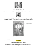
Page 15: ...te 4 Make sure helper is holding saw frame NOTE If you purchased an optional stand install it before removing saw from crate Refer to stand installation instructions 5 Push sides of crate away from saw frame to release and remove saw and set saw out of crate and place in the desired and secure position See page 18 Standing Up the Tool 6 One or more boxes of parts are attached to the frame The cord...

Page 16: ...ent damaging the Counterbalance A Counterbalance is used on Models C4 C5 and H Series to offset the weight of the carriage and saw The 6400 and 6800 models use a Counterweight system that is factory installed When unpacking a 6400 or 6800 loosen carriage lock Fig 13 move saw carriage to center Remove wood support block from bottom center of weight canister The Counterbalance on Models C4 C5 and H ...

Page 17: ...right side holes and cable aligns with saw carriage Figure 12 Installing the Counterbalance 4 Hold the Saw Carriage Page 12 securely while you loosen the Carriage Lock Fig 13 Raise the Saw Carriage until the right hole Fig 13 in the top of the Saw Carriage aligns with the eye in the end of the Counterbalance Cable Fig 13 making sure the cable is behind the Saw Carriage Fig 14 Tighten Carriage Lock...

Page 18: ...Carriage Lock Fig 13 Remove the Cable Clip Fig 15 from the Counterbalance Cable and save it for future use e g if you remove the Counterbalance in the future you will need the Cable Clip to support the tension in the Counterbalance Figure 16 Counterbalance Attached Standing Up the Tool Do not attempt to lift tool without help of an assistant With the help of an assistant stand up the tool and posi...

Page 19: ...ashers three nuts and one bolt installed Remove these items to mount the saw to the turntable on the carriage creating the saw carriage 1 Loosen the carriage lock and lower the carriage to a comfortable working height Then tighten the carriage lock securely 2 Mount the motor to the carriage by inserting the studs Fig 17 6 on the saw motor through the holes in the turntable 5 Install the washers an...

Page 20: ...w blade must be carefully matched to the materials being cut Safety Speed does not supply a blade as standard equipment on the saw Improper blade selection can result in reduced tool life inaccurate poor quality cuts and safety risks Consult with your machinery dealer or with our customer service department 763 755 1600 to determine the best blade for your cutting needs NOTE It is a good idea to h...

Page 21: ...ard before operating Page 22 7 Loosen the carriage lock and allow the saw carriage to return to the top of the guides To reduce the risk of injury do not operate the tool without the blade guard in place Installing a Blade 6400 6800 1 Observe appropriate lock out tag out procedures to insure the tool cannot accidentally be powered 2 Select the correct blade for your needs Refer to Selecting a Blad...

Page 22: ... the guides NOTE It is a good idea to have spare blades available to prevent downtime To reduce the risk of injury do not operate the tool without the blade guard in place Installing the Blade Guard aka Dust Bonnet The blade guard Fig 20 for C H series is in the box marked Saw Motor NOTE The blade guard for 6400 6800 is factory installed Always install the blade guard before operating the saw The ...

Page 23: ...adjusted to the specific blade that is mounted in the saw Install a blade then refer to Adjusting the Crosscut Rulers in the Operation Section page 31 NOTE After the saw is completely assembled you can make a simple cut to verify that the rulers are lined up correctly Installing the Cord Keeper The cord keeper keeps the cord away from the blade and away from your work piece 1 Pinch the ends of the...

Page 24: ...ord from the motor and place the plug end through the ring as shown Fig 24 Figure 24 Cord keeper installed with cord 3 Loosen the carriage lock and lower the carriage to the bottom of the guide tubes the farthest that the cord will have to be extended Lock the carriage lock in this lowered position Rubber Stopper Cord Cord Keeper Rubber Stopper Cord Keeper ...

Page 25: ...following are suggestions that give you a general idea of how a panel saw is intended to be operated No instructions can replace common sense and experience Be sure you and all operators have enough time and material to become familiar with the general operating characteristics of this tool and have FULLY READ AND UNDERSTOOD all general operating and safety instructions Capacities of the Tool Smal...

Page 26: ...st 4 100mm beyond the carriage on both sides Page 34 Fig 35 Do not crosscut work pieces that extend more than 5 feet 1520mm beyond the outermost roller on a Model C4 or C5 more than 2 feet 610mm beyond To increase available capacity for these larger panels SSM recommends using the optional Frame Extensions Page 45 Fig 49 Rip cutting Capacities The minimum length recommended for rip horizontal cuts...

Page 27: ...80TCGL Aluminum composite X X X Aluminum plate X Chipboard X X X X X Double face panels X X X X Duraply X X Gatorfoam X X Hardwood X X X X Laminated panels X X X Masonite X X X X Melamine X X X Particle board X X X X X Plexiglas up to 1 2 X X Plywood X X X X X Polycarb Lexan X X Polyester X X X Printed grain lamin X X Solid wood X X X X X Veneer X X X Vinyl X X X Always keep blades clean and sharp...

Page 28: ...moving and Reinstalling the Blade Guard Dust Bonnet Unplug Saw before adjusting The blade guard Fig 28 29 21 is attached to the carriage with torque knobs Fig 28 29 22 Remove the torque knobs to remove the guard Be sure to leave the rubber washers on the torque knobs to prevent the knobs from slipping Carriage Lock Index Pins Handle ON OFF Switch Spindle Lock Blade Guard Handle ON OFF Switch Carri...

Page 29: ...ropriate lock out tag out procedures to insure the tool cannot accidentally be powered 2 Remove the blade guard see Removing and Installing the Blade Guard and Fig 28 29 21 3 To keep the spindle from turning while you loosen the arbor bolt C H Fig 30 12 or 6400 6800 Fig 31 12 push the spindle lock 16 located on the under side of the saw motor Fig 31 6400 6800 or on top of the motor housing Fig 30 ...

Page 30: ...rclockwise 8 Use the hex or box wrench to tighten the bolt while pushing the spindle lock 9 Reinstall the blade guard 10 Loosen the carriage lock and allow the saw carriage to return to the top of the guides 11 Reconnect the power NOTE You may have to readjust the rip and crosscut rulers after changing blades or installing a re sharpened blade See Adjusting the Crosscut Rulers Figure 30 Installing...

Page 31: ...ched to the frame on each side of the saw The rip ruler is set at the factory but the two crosscut rulers must be adjusted to the specific blade that is mounted in the saw Unplug Saw before adjusting Be sure the blade is installed before following these steps 1 Remove the blade guard page 28 Fig 26 27 so the blade is exposed 2 Loosen the carriage lock and lower the carriage as shown in Fig 32 Figu...

Page 32: ...fer to the Maintenance section for regular maintenance procedures Operating Procedure Crosscutting A crosscut is a vertical cut that must always be done from the top to the bottom of a work piece as shown on page 33 Fig 34 and 35 See also General Operating Tips above and Capacities of the Tool To reduce the risk of injury do not place your hands on or under the carriage or in the path of the saw b...

Page 33: ...p of the guides and lock the carriage rip lock 12 When making cuts that are less than 1 25mm the chatter preventer guard located inside the blade guard must be resting on the work piece not on the cut off piece See page 36 Fig 39 40 If it is not positioned this way it will jam the work piece and prevent the carriage from continuing through the cut If the saw jams turn the saw OFF and wait for the ...

Page 34: ...w and completely off load it 2 Select the ripping direction from right or from left based on preference Then rotate the turntable to the ripping position as shown See Rotating the Turntable The rip measurement is set at the factory for cutting right to left The measurement indicator will need to be adjusted for left to right 3 Select the height of the saw blade above the rollers Raise or lower the...

Page 35: ... out of the saw reposition the work piece restart the motor and begin the cut again 7 As the work piece passes across the machine move to the other side and complete the cut by pulling the work piece past the saw blade Support the upper piece to keep it from pinching the blade or the kerf protector or falling away from the machine 8 Once the cut is complete turn off the motor and wait for the blad...

Page 36: ...g 39 40 If it is not positioned this way it will jam the work piece and prevent the carriage from continuing through the cut If the saw jams turn the saw OFF and wait for the blade to stop Then back the saw out of the cut Figure 39 Chatter Preventer guard in position for crosscutting C H Series shown Figure 40 Chatter Preventer guard in position for crosscutting 6400 shown Feed stock with arrows C...

Page 37: ...s Cleaning Unplug Saw before cleaning Daily clean all dust and debris from the vents in the motor housing Keep the handles clean dry and free from oil and grease Use only mild soap and a damp cloth to clean the tool because certain cleaning agents and solvents are harmful to plastics and other insulated parts Some of these include gasoline turpentine lacquer thinner paint thinner chlorinated clean...

Page 38: ... Serial Number available when calling for parts and accessories See inside cover of this manual or model serial label on top left of saw frame page 2 Fig 1 Alignment The tool is aligned at the factory to a tolerance of 1 32 8mm on Models C4 C5 H4 H5 and H6 1 64 4mm on Models 6400 and 6800 Realignment is only required if the saw is mishandled or abused or if the motor or a roller is replaced Alignm...

Page 39: ...lade should contact the Adjustment Tool If it does not then the blade is not parallel to the work piece and you should a Loosen but do not remove the four hex head nuts holding the indexing pin assembly Fig 42 24 b If burn marks appear on the left side of the work piece rotate the saw slightly clockwise until the entire face of the blade contacts the Adjustment Tool c If burn marks appear on the r...

Page 40: ...es the vertical edge of the Alignment Tool Continue to pull the carriage down if the blade does not contact the square or if the blade binds on the square the guides are not aligned Figure 43 Aligning the Guide Tubes To align the Guide Tubes 1 Remove set screw which indicates original position of guide tubes Loosen the guide bracket nuts Fig 43 but do not remove the bracket Using a dead blow malle...

Page 41: ...e frame and against the outermost rollers Position the clamps above the outermost roller 2 With the straightedge securely clamped rotate each roller to be sure that it neither jams nor has excessive clearance from the straightedge If a roller runs tight or loose to the straightedge loosen the roller nut The roller nuts are torqued and require at least an 18 in 458mm breaker bar to loosen them 3 Al...

Page 42: ...unch Stop Bar 7 32 drill bit Stop Bar Quick Stop Drill Stop Bar Quick Stop Frame Wheels The Frame Wheels Accessory allows the tool to be rolled from one location to another in the shop It includes two wheels and mounting fasteners Installation Unplug tool before making adjustments or installing accessories Bolt one wheel to each end of the frame as shown in Fig 44 45 Figure 44 Installing the Wheel...

Page 43: ...o attach the panel saw to the support wall Do not attempt to lift or lean tool without help of an assistant Installation Note Various mounting positions of fixed frame stand depending on saw model See instructions included with frame stand and next page for reference pictures 1 With the assistance of a helper lean face of saw frame toward wall Make sure saw is secure or held in place during instal...

Page 44: ...ons Figure 46 C4 Fixed Stand shown Figure 47 H4 Fixed Stand shown from back from back Figure 47A H5 Installing Fixed Stand Figure 47B Installing Fixed Stand H6 6400 6800 shown from back 6400 shown from back Figure 47C H6 and 6800 Stand Figure 47D 6400 Stand shown from back shown from back ...

Page 45: ...ol frame It includes two extensions and the necessary fasteners Extensions are recommended for cutting 4 x 8 ft 1220mm x 2440mm sheets on the Model C4 and C5 and for cutting panels longer than 10 ft 3040mm on larger tools Installation Unplug tool before making adjustments or installing accessories Attach the extensions to the back of the frame as shown in Fig 49 It is not necessary to remove any p...

Page 46: ...th the hose connection on the blade guard Installation Refer to Fig 50 51 Before beginning installation disconnect the power supply to the motor raise the carriage to the top of the guides and lock the carriage in place with the lock knob Be sure the tool frame is securely supported and cannot be tipped over during this installation procedure An additional person should support and stabilize the f...

Page 47: ...d the back of the frame to the vacuum see above specifications 6 Connect the hose end that is toward the front of the frame to the narrow end of the steel tube elbow 7 Connect the tapered end of the steel tube elbow to the outside of the plastic dust tube Operation Always turn the vacuum source on before starting the saw and turn it off when finished cutting Stop Bar The Stop Bar Accessory fits be...

Page 48: ...e tool as possible 3 Working from the back of the machine use the angle supports as templates to drill six 7 32 5 55mm holes two per bracket in the horizontal tubes of the frame 4 Insert and tighten six self tapping 20 6 35mm hex head screws to secure the angle support brackets to the frame tubes 5 Measure out from the blade and adjust the stop bar ruler by sliding it left or right inside its alum...

Page 49: ...ith the lock knob Be sure the tool frame is securely supported and cannot be tipped over during this installation procedure An additional person should support and stabilize the frame at all times during the installation 1 Attach the two mounting brackets to the long aluminum angle bar of the Quick Stop as shown in Fig 54 using the screws provided Figure 54 Installing the Quick Stop viewed from re...

Page 50: ...reach behind the carriage 4 Cut the work piece with a smooth continuous down stroke of the carriage Figure 56 Quick Stop installed Midway Fence The Midway Fence Accessory is a removable horizontal work piece support that mounts halfway up the tool frame It allows narrow work pieces to be worked at waist height The fence consists of left and right fixed brackets that mount to the frame and removabl...

Page 51: ...rusion is cut at a 45 angle The units should be pre assembled so that these beveled ends will fit against the center of the tool frame at final assembly Figure 57 Pre assembly of Midway Fence 2 Set the complete right hand fence assembly onto the tool frame as shown in Fig 58 Figure 58 Mounting the Midway Fence LEFT SIDE RIGHT SIDE ...

Page 52: ...ons between the aluminum support bracket and the cam type spacers can be adjusted by turning the bolt heads with a wrench This fit can be readjusted at any time without realigning the fence system 9 Align the fence system see below Fence Alignment 1 Disconnect the power supply to the tool 2 Remove the blade guard 3 Slightly loosen the bolts that secure the aluminum extrusion 5 Fig 51 to the rear s...

Page 53: ...nd can be quickly removed without wrenches for cutting thicker material Installation Unplug tool before making adjustments or installing accessories 1 Attach the top and bottom support brackets Fig 60 with four 5 16 x 3 4 7 9mm x 19 05mm cap screws and nuts The top bracket is marked T and the bottom bracket is marked B 2 Insert the round vertical tube up through the top bracket and then lower it d...

Page 54: ...54 ...

Page 55: ... All models available in optional 220 240V 50 60 hertz ACCESSORIES NOTE SAW BLADES listed on page 27 BE PORTABLE Description Part WHEELS all models H10 FIXED STAND C4 H4 H5 H20 H6 H25 6400 6420 6800 6820 FOLDING STAND C4 H22 C5 H23 MEASURE WITH ACCURACY QUICK STOP C4 C5 5 ft C6460 H4 H5 H6 6400 6800 8 ft H6460 DIGITAL QUICK STOP C4 C5 C6460 DRO H4 H5 H6 6400 6800 H6460 DRO LASER LINE C4 C5 H4 H5 H...

Page 56: ...13943 LINCOLN ST NE HAM LAKE MN 55304 763 755 1600 Fax 763 755 6080 sales safetyspeed com www SafetySpeed com 093016 ...

Reviews: