LIFT MODEL VISION AS 300 Rev001
6-12
9.
6
OPERATORS CONTROL PANEL
6.1
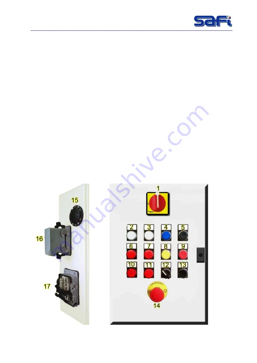
Electric panel
The electric control panel is the "semi-automatic" type to allow the operator to manage rise and
descent operations.
It means that to move the car is NOT necessary to hold the button (“UP” or “DOWN”) pushed.
The electric panel consists of a cabinet with door, fitted with internal hinges and lock.
The on/off switch may be padlocked and has a door-lock system which prevents the door from
being opened before the power supply has been cut off to all the circuits inside the control
panel.
All connection points of the other equipment (remote-control devices, protective relays,
transformer) are in any case protected against direct or indirect accidental contact.
6.2
Electrical connections
•
Take care of the electric panel mounted inside the elevator.
10. Check the value of the supply voltage and the available power.
11. Check the voltage of the electric motors and of the control-panel transformer. If
necessary change voltage.
12. Connect the installation to the ground.
13. Connect the electric panel to the power supply.
14. Set the cut-out switch to the "I" position.
Summary of Contents for VISION AS 300
Page 2: ......
Page 4: ......
Page 43: ...LIFT MODEL VISION AS 300 Rev001 7 4 Fig 7 1 Dimension...
Page 68: ...LIFT MODEL VISION AS 300 Rev001 12 1 12 WIRING DIAGRAMS Fig 12 1 Wiring diagram Power supply...
Page 69: ...LIFT MODEL VISION AS 300 Rev001 12 1 Fig 12 2 Wiring diagram Motor power supply...
Page 70: ...LIFT MODEL VISION AS 300 Rev001 12 2 Fig 12 3 Wiring diagram Emergency circuit...
Page 71: ...LIFT MODEL VISION AS 300 Rev001 12 3 Fig 12 4 Wiring diagram Auxiliary...
Page 72: ...LIFT MODEL VISION AS 300 Rev001 12 4 Fig 12 5 4 Wiring diagram Auxiliary PLC logo expans...
Page 73: ...LIFT MODEL VISION AS 300 Rev001 12 5 Fig 12 6 Auxiliary circuit...
Page 74: ...LIFT MODEL VISION AS 300 Rev001 12 6 Fig 12 7 Wiring diagram Connectors C1 C2 C3...
Page 75: ...LIFT MODEL VISION AS 300 Rev001 12 7 Fig 12 8 Wiring diagram Terminal box electric panel...
Page 76: ...LIFT MODEL VISION AS 300 Rev001 12 8 Fig 12 9 Wiring diagram Cable call floor...
Page 77: ...LIFT MODEL VISION AS 300 Rev001 12 9 Fig 12 10 Wiring diagram Floors call connection...
Page 78: ...LIFT MODEL VISION AS 300 Rev001 12 10 Fig 12 11 Wiring diagram Box floor call connection...
Page 79: ...LIFT MODEL VISION AS 300 Rev001 12 11 Fig 12 12 Wiring diagram Box Fencing connection...
Page 80: ...LIFT MODEL VISION AS 300 Rev001 12 12 Fig 12 13 Wiring diagram Cable fancing call...
Page 81: ...LIFT MODEL VISION AS 300 Rev001 12 13 Fig 12 14 Main electrical box components...
Page 82: ...LIFT MODEL VISION AS 300 Rev001 12 14 Fig 12 15 Material list 1...
Page 83: ...LIFT MODEL VISION AS 300 Rev001 12 15 Fig 12 16 Material list 2...


