9
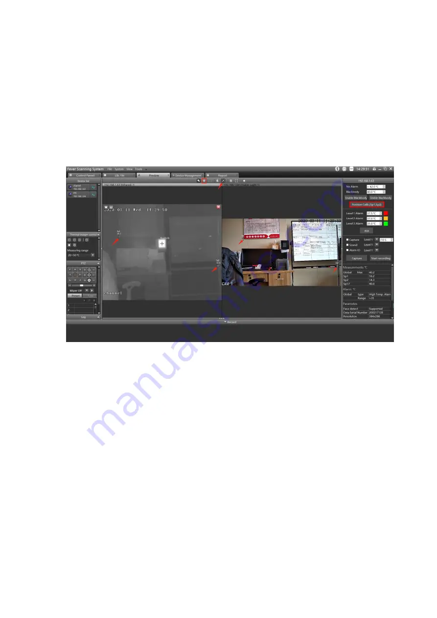
example, Sp1 is the upper left corner of the Blackbody, Sp2 is a point on the bracket (refer to
the picture below), and click position correction (Sp1, Sp2).
3) Test: Please let somebody walks around in front of the image to see whether the position of
the picture alarm frame is consistent. If not, readjust the position of Sp1 and Sp2. Then click
position correction Sp1, Sp2.
4) After the temperature alarm overlaps in the same position of the visible image, click the
real-time mark mode to hide the mark points Sp1, Sp2 and reference points.
Figure 7 Set the points to match the TI and visible camera preview view field
5.4 Smart (Face detection) Temperature Measurement Setting
Activate Smart Temperature Measurement Setting by opening “Tools”, then select “AI Detect”.


