Q 013 Notice d’instructions TOURELLES D’EXTRACTION
23/12/2015
RECEPTION ET MANUTENTION
L’utilisation de protections corporelles est
recommandée pour éviter les blessures
dues
aux
risques
électriques
et
mécaniques (bords coupants…).
Vérifier l’état du colis et son contenu lors de la
livraison. Si besoin, apporter des réserves auprès
du transporteur dans les 48h.
Avant toute expédition, nos appareils sont
contrôlés sous tension afin de vérifier, l’équilibrage
de la tourelle, le moteur et sa tension.
Equipment reception and handling
Use necessary personal protective equipment
to avoid injuries from mechanical hazards (.i.e.
cutting edges).
Check the condition of the packaging and contents at
the time of delivery. Any reservations should be
reported to the distributor within 48 hours after delivery.
Before being distributed, the electric equipment’s
components, performance, and balance are tested
extensively.
CARACTERISTIQUES TECHNIQUES
Les caractéristiques de l’appareil :
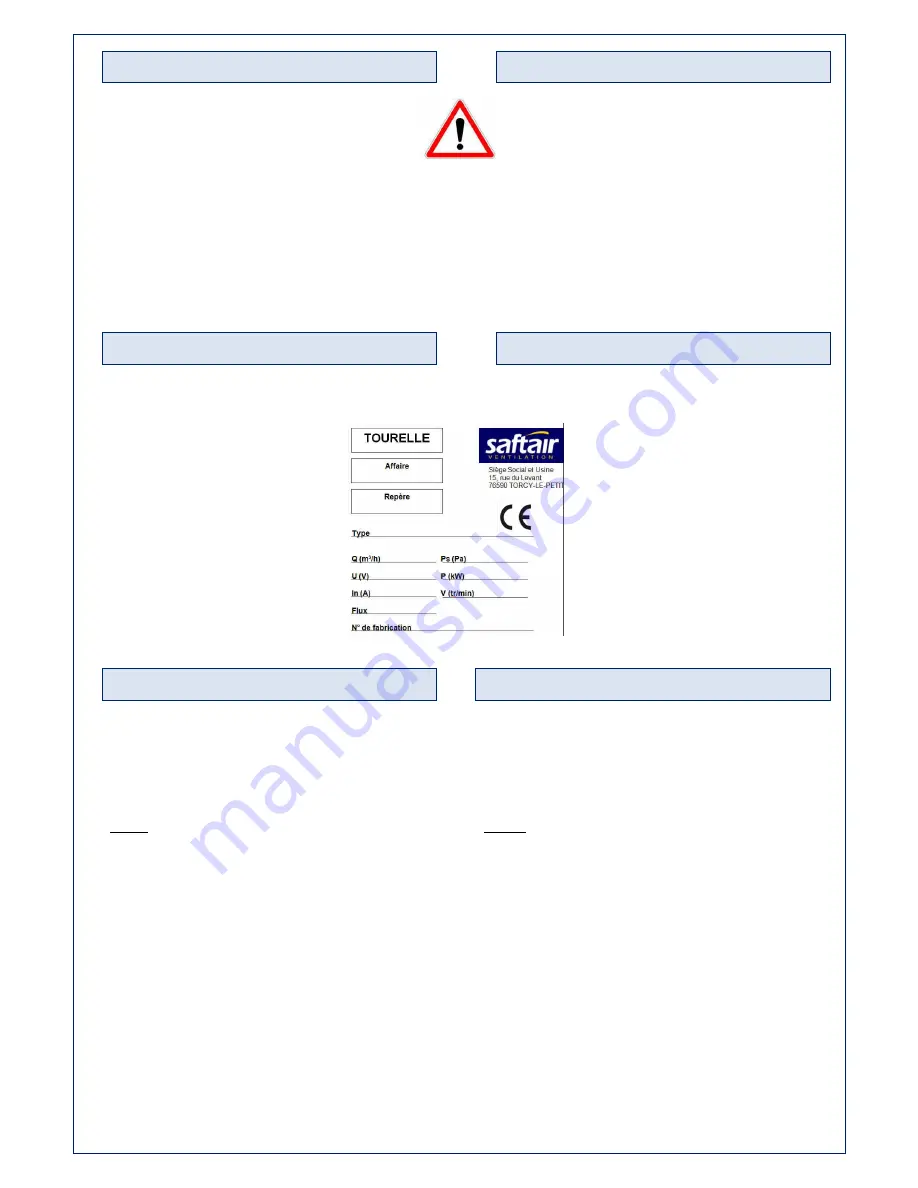
se reporter à la plaque signalétique
fixée sur l’appareil.
Les caractéristiques de l’appareil :
puissance,
intensité,
vitesse,
tension et fréquence, figurent sur
l’étiquette signalétique.
Le niveau sonore de ces machines,
donné à une distance de 8 m en
champ libre hémisphérique est
inférieur à 70 dB (A).
Technical characteristics
Please, refer to the CE-marking label
attached to the equipment for the
technical specifications.
Power, amperage, fan rotation speed,
voltage, and frequency (Hz) are marked
on the descriptive label.
The sound level of these machines is
less than 70 dB (A) and measured at a
distance of 8 m in a free hemispherical
field.
MISE EN PLACE
La tourelle sera fixée HORIZONTALEMENT sur son
support à l’aide des quatre trous Ø 14 de fixation
prévus à cet effet aux quatre angles de l’embase.
Nota : Un angle d’inclinaison de 6° maximum est
admis. (Illustration 2)
Dans le cas d’une tourelle munie d’un coffret de
relayage monté, le coffret de relayage est câblé et
emballé sur le capot de la tourelle.
Pour installer le coffret de relayage sur la colonne :
1)
Dévisser le capot de la tourelle
2)
Faire glisser l’ensemble support + coffret de
relayage le long de la colonne (ATTENTION AU
CABLE)
(Illustration 3)
3)
Remonter ensuite le capot avec les quatre
écrous
Installation
The centrifugal tower must be horizontally fixed on its
support to the four corners of the base using four
fixing holes Ø 14 mm integrated in the design.
Note : An angle of deviation of 6° or less is allowed.
(Illustration 2)
In the case of an extractor provided with a relay box,
the relay box is wired and packed on the cover of the
tower.
To install the relay box :
1)
Remove the cover
2)
Slide the support + the relay box along the column
(Please make sure the cable does not get stuck)
(Illustration 3).
3)
Then install the cover with the four screws


