Chapter 3: Wiring
Firmware – S1043
Revision: 2 (9/98)
34
© Saftronics, Inc.
Installing an AC Reactor
If the Inverter is connected to a large capacity power transformer (600 kW or more) or the Power Factor Correction
Capacitor is switched, an excessive peak current may flow through the input power circuit, causing the converter unit
to break down.
To prevent this, install an optional AC Reactor on the input side of the Inverter or a DC reactor to the DC reactor
connection terminals.
This also improves the power factor on the power supply side.
Installing a Surge Absorber
Always use a surge absorber or diode for inductive loads near the Inverter. These inductive loads include Magnetic
Contactors, electromagnetic relays, solenoid valves, solenoids, and magnetic brakes.
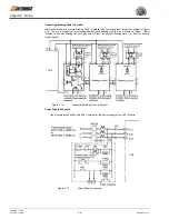
Wiring the Power Terminals of Inverters with 18.5 to 300 kW Outputs
•
For 200 V class Inverters of 18.5 to 75 kW or 400 V class Inverters of 18.5 to 45 kW, connect the r and
s
terminals to the R and S terminals respectively. (These are shorted by a short-circuit bar for shipping.)
•
For 400 V class, 55 to 300 kW, connect the r and
s
400 terminals to the R and S terminals respectively. (These
are shorted by a short-circuit bar for shipping.)
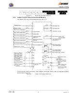
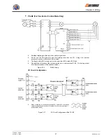
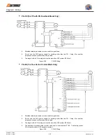
Installing a Noise Filter on Power Supply Side
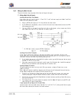
Install a noise filter to eliminate noise transmitted between the power line and the Inverter.
•
Wiring Example 1
Figure 3.8
Correct Power Supply Noise Filter Installation
•
Wiring Example 2
Figure 3.9
Incorrect Power Supply Noise Filter Installation
VG5
VG5
VG5

