72
DOCUMENT SSE-0000077399-01 - V
Anti-tamper and anti-pulling switches
–
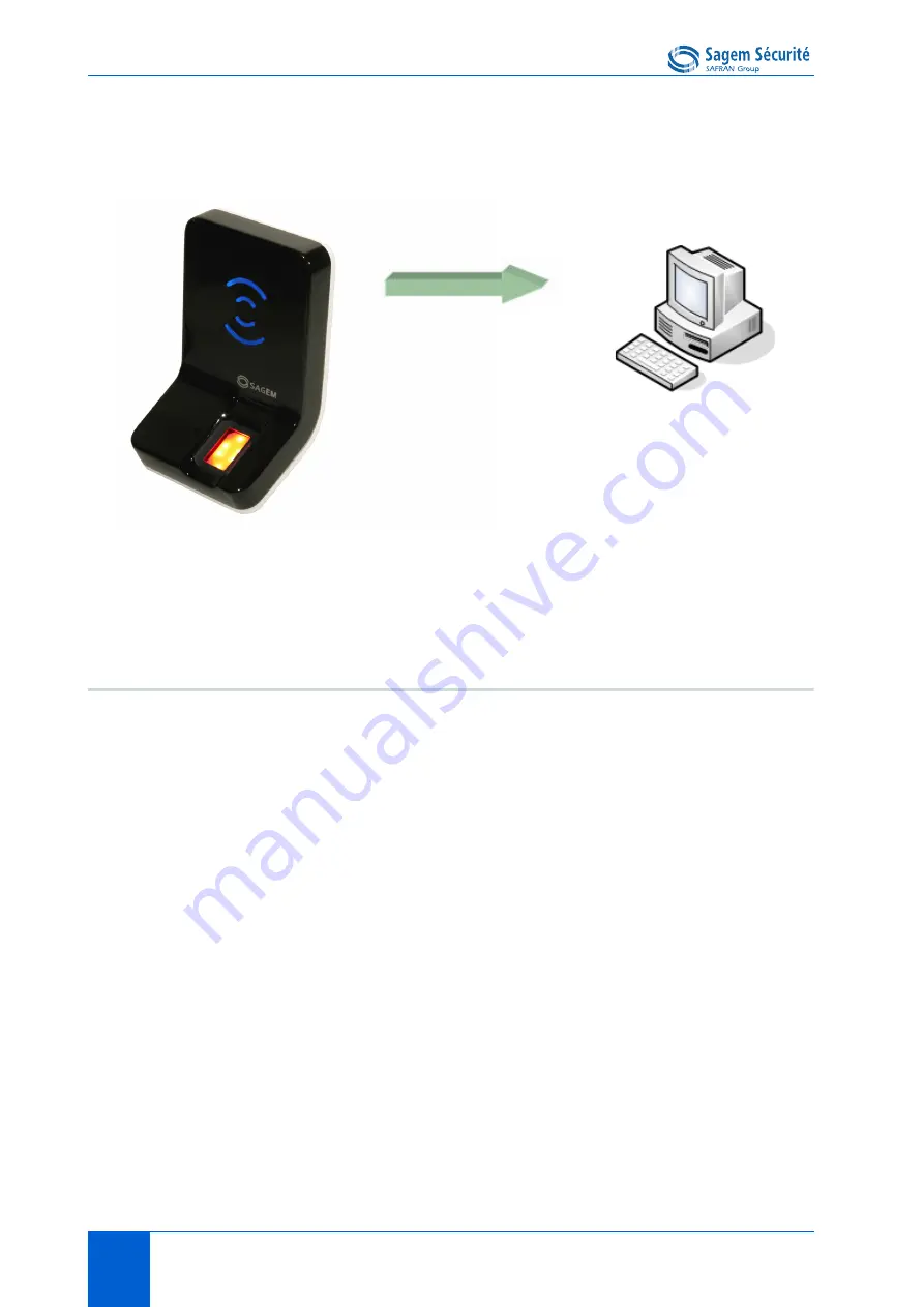
Figure 8 • 4: Tamper switch and anti-pulling switches
Configuration keys
To send an alarm on an output (Ethernet, RS485, Wiegand, Dataclock,
Wi-Fi
TM
), the corresponding interface must be activated otherwise no alarm
will be sent.
Because RS485, Wiegand, and Dataclock are multiplexed on the same lines,
only one of these protocols shall be enabled at one time, else priority is given
to Wiegand, then Dataclock, then RS485.
Those configuration keys are:
•
app/send ID wiegand/enabled,
•
app/send ID dataclock/enabled,
•
app/send ID serial/enabled,
•
app/send ID serial/mode (to select RS485 link),
•
app/send ID UDP/enabled,
•
app/send ID ethernet/mode (to choose between UDP or TCP),
•
app/send ID ethernet/SSL enabled (Please refer to SSL Solution for
MorphoAccess
®
documentation).
Setting the configuration key a
pp/tamper alarm/level
to an appropriate value
configure security switch management feature.
Alarm message
•
Ethernet (UDP/TCP/SSL)
•
RS485
•
Wiegand
•
Datadock
•
Wi-Fi
TM
(UDP/TCP/SSL)
Summary of Contents for MorphoAccess J-Bio
Page 13: ...SECTION 1 INTRODUCTION...
Page 19: ...SECTION 2 TERMINAL PRESENTATION...
Page 25: ...SECTION 3 TERMINAL CONFIGURATION...
Page 39: ...SECTION 4 STAND ALONE MODES NETWORKED OR NOT...
Page 49: ...SECTION 5 ACCESS CONTROL BY IDENTIFICATION...
Page 53: ...SECTION 6 ACCESS CONTROL BY AUTHENTIFICATION...
Page 67: ...SECTION 7 PROXY MODE...
Page 71: ...SECTION 8 TERMINAL CUSTOMIZATION...
Page 89: ...SECTION 9 MAN MACHINE INTERFACE...
Page 103: ...SECTION 10 APPENDIX...
Page 115: ...SECTION 11 SUPPORT...


