ENGLISH
(*) PRESSURE FOR TEST CHECKER:
With the HVLP nozzle You must not exceed the maximum inlet pressure of 1.8
bar. An excess pressure will create an additional over spray and will reduce the transfer.
10. Air Nozzle Kits
Air Nozzle Kits
DVR TITANIA, DVR AQUA, DVR HVLP and DVR CLEAR
.
Nozzle
Air
consumption
Pressure
DVR TITANIA
320 litres / minute
2 bar
DVR AQUA
290 litres / minute
2 bar
DVR HVLP
465 litres/minute
2 bar (*)
DVR CLEAR
305 litres/minute
2 bar
11. Start-up
Before each start-up
and especially after cleaning or repairing the unit, a check must be made that
all its
elements
are
securely tightened
.
If maintenance or repair work is to be carried out, the gun must be depressurised before work
begins (without air pressure). Should this safety measure not be observed, this may lead to
malfunctions, personal injury and accidents, which may prove to be fatal. SAGOLA S.A.
does not
accept any responsibility for the consequences of any non-compliance with these safety regulations.
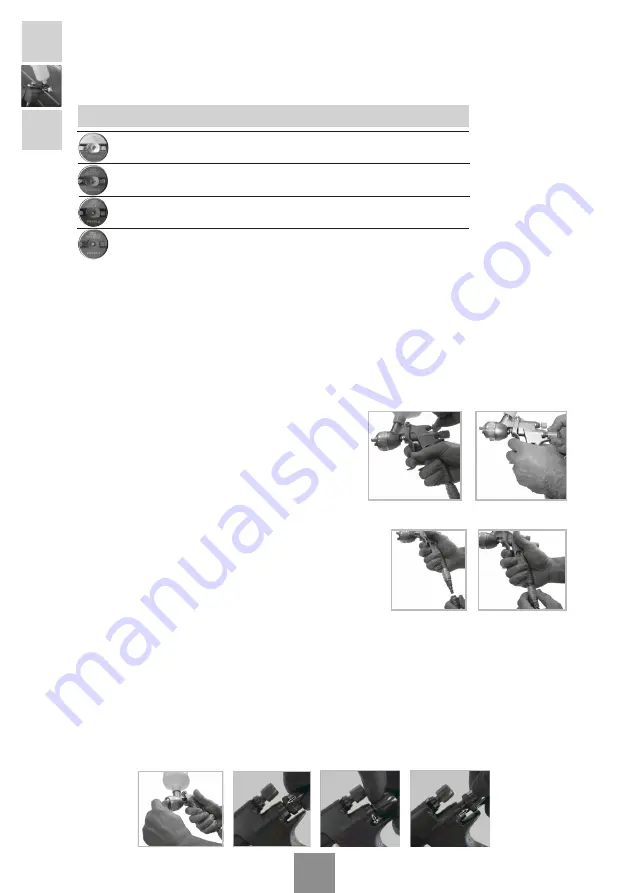
Open the spray width
(No.10)
and product regulators
(No.20) completely (without removing these from their
housing) by turning these anticlockwise. (See Fig.1
and Fig.2)
Place the pistol on a support so that the axis of the
tank is vertical.
Pour the product
to apply into
the tank
. Until the level is a maximum of 20-25 mm. below the edge
of the tank.
Tighten the filler cap firmly.
In the version with the non-drip
cap, tip it forward (paint up) or back (paint down) as
necessary.
Connect the gun to the compressed air network.
(See Fig.3)
Adjust the air pressure in the network regulator
in order to compensate for any pressure drop in
the network (estimated at 0.6 bar for each 10 m of hose).
Adjust the air pressure in the air nozzle by operating the flow regulator
(see Fig.4), until the
required quality of finish is obtained (better finishes are not obtained with higher spraying pressu-
res and these lead to lower performance and worse product transfer).
Position the air nozzle spraying orifices
appropriately (when an imaginary line is drawn through the
2 lugs (see Fig.5), this must be parallel or perpendicular to the floor). Fully close the product
regulator by turning it clockwise (see Fig.6). Turn the product regulator until the “0” coincides with
the arrow (see Fig.7); and perform the desired application test, adjusting the product regulators
(see Fig.8) and range as follows:
Fig.1
Fig.2
Fig.3
Fig.6
Fig.7
Fig.8
Fig.5
Fig.4


