


ENGLISH
11.5. Application distance
Adjust the distance between the air nozzle and the object to cover to
between 10 and 20 cm.
, depending on the application, in accordance with
this, the product to be applied and working conditions, in order to increase
transfer and obtain a reduction in the amount of mist in accordance with
the air nozzle used in each case.
12. Maintenance
In order to carry out maintenance, repairs or cleaning,
first disconnect the unit from the compres-
sed air distribution network.
Do not apply excessive force or inadequate tools for maintaining and cleaning the unit. Some
repairs must be done with special tools on some occasions.
In these cases, you must contact the
Customer Service of SAGOLA
. Any handling of this product
by non-authorised personnel would render the warranty null and void.
The unit must be overhauled on a periodic basis to check
the status of its components and
replace these when they are not in perfect condition.
IN ORDER TO OBTAIN THE BEST POSSIBLE RESULTS, ALWAYS USE
ORIGINAL SPARES. ENSURE TOTAL INTERCHANGEABILITY,
SAFETY AND OPERATION.
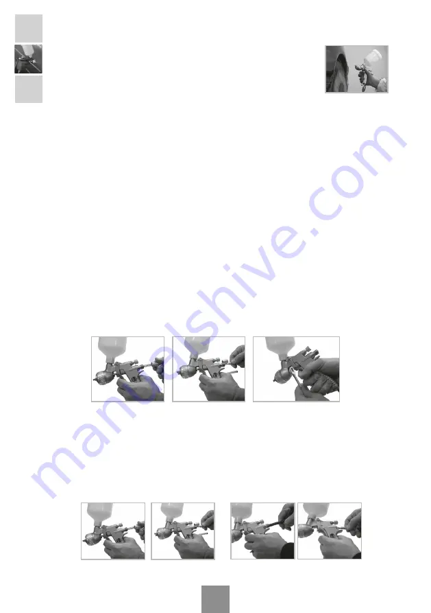
12.1. Changing the self-adjusting Packing gland
The needle gaskets
that form part of the packing gland are gun components that should be
replaced when malfunctions occur or when there is a loss of air tightness
.
Gun head packing gland:
In order to replace the packing gland, remove the product regulator
(No.20) (see Fig.1), and extract the product needle and spring fitted with its stop (see Fig.2). With
a 13 mm fixed wrench, remove the packing gland (No.9) to be replaced. Replace the packing gland
and reassemble in the reverse order (see Fig.3).
Changing seat valve:
For removal of the valve seat; remove the product regulator (No.20) and
extract the product needle and spring fitted with its stop. (See Fig.4). With a 9 mm Allen wrench,
remove the guide box (No.22), extracting the valve spring and the valve (see Fig.5); after take the
key assembly (No.27) supplied with the gun and proceed to remove the valve seat (No.23) with
hook key. (See Fig.6)
For assembly, follow the reserve procedure. (see Fig.7)
Fig.1
Fig.2
Fig.4
Fig.5
Fig.3


