background image

10

INSTALLATION AND OPERATION

HOW TO USE THE GUN SAFETY

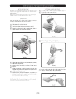
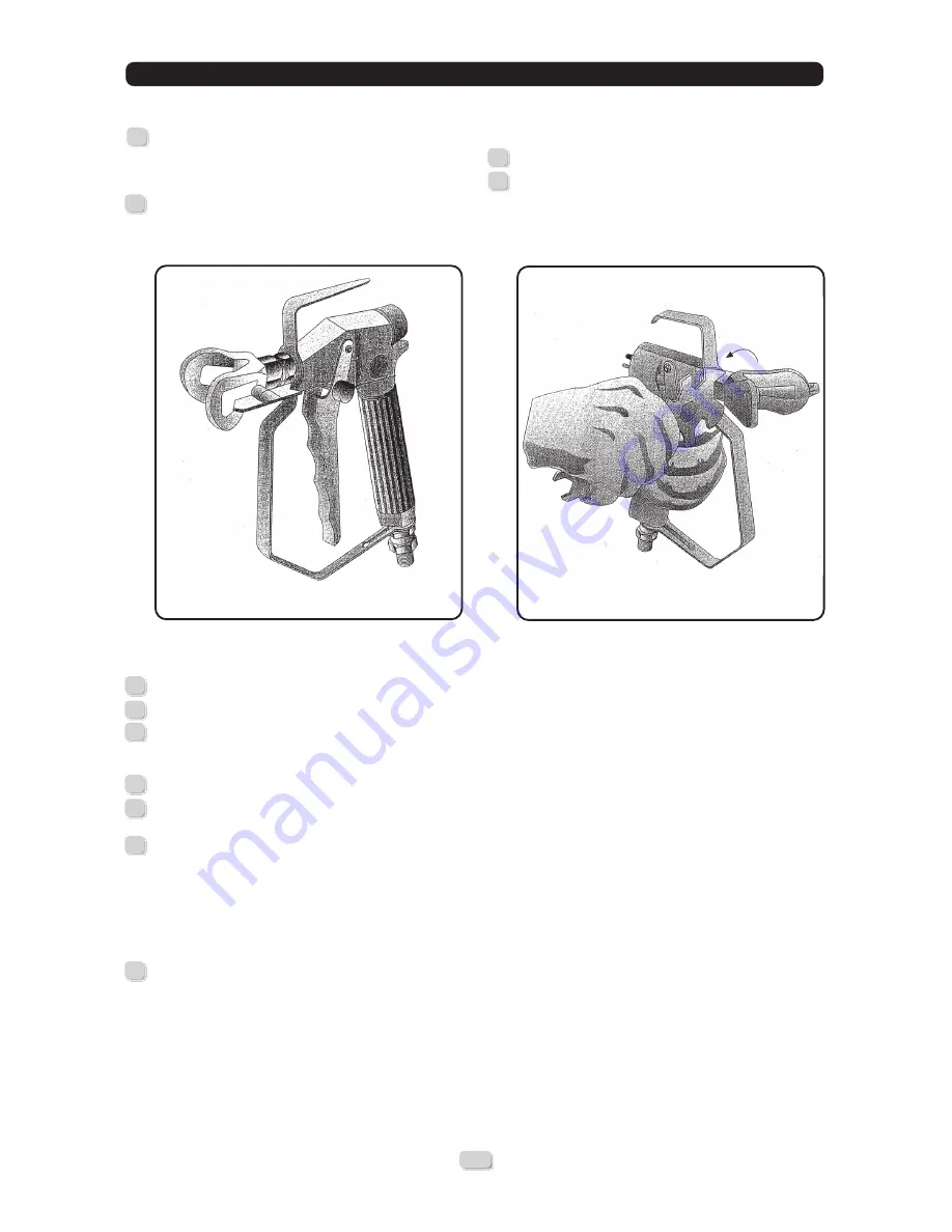
In order to engage the safety (block the opening in the trigger 

of the gun), move the trigger forward (locked position) and 

turn the lever (no. 1 - figure 2) until it butts against the gun 

body. Check that the trigger is locked.

In order to disengage the gun safety, push the trigger forward 

(closed position) and turn the lever (no. 1 - figure 2) until it 

butts against the trigger itself. 

HOW TO USE THE GUN

Connect a fluid hose (with grounding wire) to the gun inlet.

Without installing the tip, start up the pump.

Remove the product used for cleaning the pump. Prime the 

unit with the product and apply to pump as indicated in the 

instruction manual.

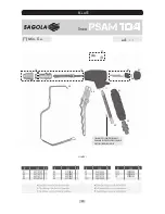
Unthread the guard and nut.

Place the spray tip and locking seal together with the nut and 

guard. Tighten firmly.

Start up the pump. Adjust the pressure until the fluid comes 

out completely in the form of a spray. Use the least pressure 

necessary. A higher pressure will cause excessive wear in the 

material and premature wear of the tip and locking seat. If 

you need higher product flow, take a tip with a larger tip. If 

it is not possible to spray the product correctly, use a smaller 

size tip until the correct size is determined for the required 

coat thickness and optimum spraying conditions.

Pull the trigger in such a way that it is completely open or 

completely closed. Keep the gun at a distance of 200-300 

milimetres  from  the  working  surface.  Move  the  gun 

perpendicularly  to  the  surface  at  the  appropiate  speed, 

overlapping paint strokes.

ADJUSTING THE SPRAY JET

In order to adjust the spray jet correctly, do the following:

Follow the decompression procedure described on page 11.

Loosen the tip support nut (figure 3). Turn the tip guard and 

place the groove in the horizontal position in order to obtain 

a vertical fan.

ACCESSORIES SUPPLIED WITH THE GUN

Filter 100 mesh (yellow)

Multiple gun wrench

Hexagonal female wrench

7

6

5

4

3

1

2

1

2

1

2

FIGURE 2

FIGURE 3

Summary of Contents for PSAM 104

Page 1: ...n de produit d autres blessures graves d incendie ou d une détérioration du matériel placé alentour NE JAMAIS modifier quelque partie de l appareil que ce soit toute modification entraîne un fonctionnement défectueux VÉRIFIEZ régulièrement les constituants de l appareil de pulvérisation réparez ou remplacez les pièces endommagées ou usées Ce pulvérisateur peut développer une PRESSION MAXIMUM DE TR...

Page 2: ...el funcionamiento del difusor seguir el procedimiento de descompresión y luego retirar la boquilla Regular la presión para la bomba en el valor más bajo posible Dirigir la pistola hacia un cubo metálico puesto a tierra Retirar el cerrojo de la pistola y accionar el gatillo El chorro debe ser inestable y remolinante Si el chorro sale regularmente reemplazar el difusor inmediatamente Protector de la...

Page 3: ...luido salga completamente pulverizado Utilizar la menor presión necesaria Una presión mayor ocasiona un gasto excesivo de material y un desgaste prematuro de la boquilla y asiento de cierre Si necesitamos mayor caudal de producto coger una boquilla de paso mayor Si no conseguimos pulverizar el producto correctamente disminuir el paso de boquilla hasta determinar la boquilla adecuada para obtener e...

Page 4: ...ctamente con disolvente de limpieza en la absorción de la bomba Poner la bomba en marcha a una presión lo más baja posible Sujetar la pistola fuertemente contra un lado del cubo metálico de disolvente puesto a tierra correctamente Apoyar el guardamanos de la pistola contra el lateral del cubo Quitar el seguro de la pistola y apretar el gatillo de la pistola apuntando contra el lateral del cubo Dej...

Page 5: ...o Colocar cierre de seguridad de la pistola Girar la maneta 180º nº1 figura 8 Quitar el seguro de la pistola Apretar el gatillo de la pistola dentro de un cubo metálico puesto a tierra apuntando contra las paredes del mismo para eliminar la obstrucción Soltar gatillo de la pistola Nota El cubo metálico de recogida de producto debe estar puesto a tierra correctamente Colocar de nuevo el seguro de l...

Page 6: ...4919 1 04 87460703 1 05 51910015 1 06 55610003 1 07 56418465 1 08 53910103 1 09 56418464 1 10 56418230 1 11 54210273 1 12 1 30010008 1 12 2 30010009 1 12 3 30010010 1 15 49000353 1 07 10 15 09 05 04 01 11 08 06 12 1 BLANCO WHITE BLANC 2 AMARILLO YELLOW JAUNE 3 ROJO RED ROUGE 02 03 ed 11 Min 5 u línea ...

Page 7: ... de la presente advertencia puede causar heridas graves que pueden conllevar la muerte El paso de producto a gran velocidad en la bomba y en las mangueras crea electricidad estática y puede provocar chispas Estas chispas pueden producir fuego en los vapores de solvente y en el producto aplicado en las partículas de polvo y en otras sustancias inflamables ya sea que se efectúe la aplicación en el i...

Page 8: ...lquier deficiencia no imputable a la fabricación del aparato Así mismo se perderá la GARANTÍA cuando se constate que el aparato ha sido manipulado por personas ajenas a nuestro Servicio de Asistencia Técnica Esta GARANTÍA no respalda los compromisos adquiridos con cualquier persona ajena al Servicio Técnico Servicio de Asistencia Técnica Tel 34 945 214 150 Fax 34 945 214 147 En caso de avería dura...

Page 9: ...ard a metal bucket which is properly grounded Remove the gun safety catch and press the trigger The jet should be unstable and swirling If the jet is even replace the diffuser immediately Tip protector ALWAYS keep the tip protector in its place on the gun whilst spraying The protector gives warning of the risk of products being injected onto the skin and assists in reducing this danger but it does...

Page 10: ...ly in the form of a spray Use the least pressure necessary A higher pressure will cause excessive wear in the material and premature wear of the tip and locking seat If you need higher product flow take a tip with a larger tip If it is not possible to spray the product correctly use a smaller size tip until the correct size is determined for the required coat thickness and optimum spraying conditi...

Page 11: ...aint solvent in the suction system of the pump Start up the pump at the lowest pressure possible Secure the gun firmly to the side of the correctly grounded metal vessel of solvent Rest the trigger guard against the side of the vessel Remove the gun safety and pull the trigger pointing the gun at the side of the vessel Allow the product to circulate until cleaning is complete Note Replace the clea...

Page 12: ...ing the cap Swivel tip Engage the gun safety Turn the lever 180º no 1 figure 8 Disengage the gun safety tighten the gun trigger inside the grounded metal vessel pointing this towards the sides of the vessel to remove the obstruction Release the gun trigger Note The metal vessel used to collect the product must be correctly grounded Engage the safety once more Turn the lever no 1 figure 8 again 180...

Page 13: ...14919 1 04 87460703 1 05 51910015 1 06 55610003 1 07 56418465 1 08 53910103 1 09 56418464 1 10 56418230 1 11 54210273 1 12 1 30010008 1 12 2 30010009 1 12 3 30010010 1 15 49000353 1 07 10 15 09 05 04 01 11 08 06 12 1 BLANCO WHITE BLANC 2 AMARILLO YELLOW JAUNE 3 ROJO RED ROUGE 02 03 ed 11 Min 5 u línea ...

Page 14: ... lights on or off Failure to observe this warning may cause severe injuries and possible loss of life The passage of product at high speeds through the pump and the hoses may cause sparks These sparks can set fire to the solvent vapours and to the product being applied to the powder particles and other inflammable substances whether application takes place indoors or outdoors and there is a risk o...

Page 15: ... normal wear and tear and in general any deficiency not attributable to manufacture Likewise the GUARANTEE will become invalid should be observed that the apparatus has been handled by persons other than ourTechnical Service personnel This GUARANTEE does not support any commitment made by any person other than our Technical Service personnel Technical Service Personnel Tel 34 945 214 150 Fax 34 94...

Page 16: ...terrompt le jet et réduit le risque d injection quand la buse n est pas en place Pour vérifier le fonctionnementdudiffuseur suivrelaprocédurededécompression puis retirer la buse Régler la pression pour la pompe sur la valeur la plus basse possible Orienter le pistolet vers un seau métallique relié à la terre Retirer le verrou du pistolet et actionner la détente Le jet doit être instable et en tour...

Page 17: ...sion pour que le fluide sorte du pistolet totalement pulvérisé Utilisez la pression nécessaire la puls faible possible Une pression trop forte provoque un gaspillage de produit et une usure prématurée de la buse et l embase de fermeture Si un débit supérieur est nécessaire utilisez une buse plus grande Si le produit n est pas correctement pulvérisé diminuez le diamètre de la buse pour rechercher l...

Page 18: ... terre et contenant du dissolvant à làbsorption de la pompe Mettre la pompe en marche à la pression la plus basse possible Maintenir fermement le pistolet contre la paroi du seau métallique raccordé à la terre Appuyez le protège mains du pistolet contre la paroi du seau Retirez la sécurité du pistolet et appuyez sur la détente du pistolet en visant la paroi du seau Laissez le produit circuler pour...

Page 19: ...Mettez la sécurité du pistolet Tournez la manette 180º nº 1 figure 8 Enlevez la sécurité du pistolet Appuyez la détente du pistolet dans un seau métallique raccordé à la terre en visant contre la paroi du seau afin d èliminer l obstruction Làchez la détente du pistolet Remarque Le seau métallique destiné pa recuellir le produit doit ètre correctement raccordé à la terre Remettez la sécurité du pis...

Page 20: ...1 04 87460703 1 05 51910015 1 06 55610003 1 07 56418465 1 08 53910103 1 09 56418464 1 10 56418230 1 11 54210273 1 12 1 30010008 1 12 2 30010009 1 12 3 30010010 1 15 49000353 1 07 10 15 09 05 04 01 11 08 06 12 1 BLANCO WHITE BLANC 2 AMARILLO YELLOW JAUNE 3 ROJO RED ROUGE 02 03 ed 11 Min 5 u línea ...

Page 21: ...raîner la mort Le passage du produit à grande vitesse dans la pompe et dans les tuyaux crée de l électricité statique pouvant provoquer l apparition d étincelles Ces étincelles sont susceptibles d enflammer les vapeurs de solvants contenus dans le produit appliqué les particules de poussière et autres substances inflammables que l application ait lieu à l intérieur ou à l extérieur et peuvent être...

Page 22: ... même la GARANTIE ne sera plus valable si l on constate que l appareil a éte manipulé par des personnes n appartenant pas á notre Servce d Assistance Technique Cette GARANTIE n endosse pas les compromis acquis avec n importe quelle personne n appartenant pas au Service Technique Service d Assistance Technica Tel 34 945 214 150 Fax 34 945 214 147 En cas de panne pendant la période de GARANTIE attac...

Page 23: ...hat Kaufdatum Data de Compra Data di aacquisto E mail Sello Stamp Cachet Stempel Selo Timbro Tel Fax GUARANTEE C0NDITIONS CONDITIONS DE GARANTIE CONDICIONES DE GARANTÍA CONDIÇÕES DA GARANTIA CONDIZIONI DI GARANZIA GARANTIEBENDINGUNGEN Adquirido por Purchased by Acquis par Erworben durch Adquirido por Acquistato da Domicilio Address Adresse Wohnsitz Endereço Indirizzo Población Town Ville Ortschaft...

Page 24: ...ISCHER DIENST PROFESSIONNELLE REPARATURGARANTIE SERVIÇO DE ASSISTÊNCIA TÉCNICA GARANTÍA DE REPARAÇAO PROFISSIONAL SERVIZIO DI ASSISTENZA TECNICA GARANZIA DI RIPARAZIONE PROFESSIONALE Tel 34 945 214 150 Fax 34 945 214 147 e mail sat sagola com 543 107 77 SAGOLA S A Urartea 6 01010 Vitoria Gasteiz ESPAÑA Tel 34 945 214 150 Fax 34 945 214 147 e mail sagola sagola com web www sagola com Ref 30170103 ...

Reviews: