ENGLISH
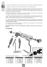
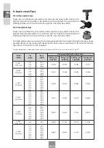
9. Nozzle chart (Tips)
9.1. Airless swivel caps
These tips are defined by the product tip size and the spray width. Choose the
right tip size and spray width in accordance with the product to be sprayed and
working surface. Each tip size defines a specific size and spray width.
9.2. Fixed airless tips
These tips are defined by the product orifice and the spray width. Choose the
right tip size and spray width in ac-cordance with the product to be sprayed and
working surface. Each tip size defines a specific size and spray width.
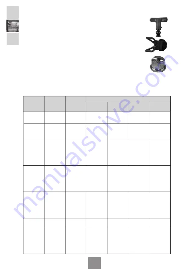
The table below serves as a guide for the flows generated by fixed caps at certain pressures. It also
provides details of the spray width developed by these tips at a distance of 30 centimetres from
the surface on which it is to be supplied.
The spray width obtained is based on paint with a viscosity of 20 seconds in FORD CUP No. 4, at a pressure of 112 Kg/cm2.
Outlet
orifice
0.007”
0.18 mm.
0.106
0.152
0.186
0.217
15
25
40
114
140
165
0.009”
0.28 mm.
0.147
0.208
0.255
0.296
15
25
40
65
114
140
178
235
0.011”
0.28 mm.
0.225
0.300
0.380
0.450
10
15
25
40
50
65
80
101
127
153
190
216
254
292
0.013”
0.33 mm.
0.340
0.450
0.575
0.680
10
15
25
40
50
65
80
101
127
153
203
229
267
318
0.015”
0.38 mm.
0.450
0.600
0.750
0.870
10
15
25
40
50
65
80
101
127
178
216
254
279
330
0.018”
0.46 mm.
0.680
0.940
1.125
1.350
10
15
25
40
50
65
80
127
153
178
254
279
330
381
0.016”
0.41 mm.
0.525
0.750
0.900
1.050
65
300
35 Kg/cm
2
500 PSI
70 Kg/cm
2
1000 PSI
105 Kg/cm
2
1500 PSI
140 Kg/cm
2
2000 PSI
Tip
angle
Spray
width
Flow generated by the tip (L/min)

