Hardware Manual for the PCD3 Series│Document 26/789; Version E 5│31.01.2005
Saia-Burgess
Controls Ltd.
Addressing and cabling rows
Orientation guide
2-7
2
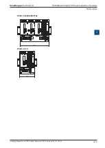
Each additional PCD3.C100/C200 module holder provides space for 4 further I/
O modules; at the end of the bus, a PCD3.C110 provides space for 2 further I/O
modules. The connection to the next row is via the PCD3.K106 26-core extension
cable.
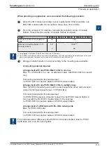
Forces arising with too small cable radii (smaller than the natural radius) may damage
the plug connection.
The extension cables must not be plugged in or removed with the controller
connected to the power supply.
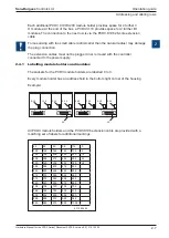
2.4.1 Labelling module holders and modules
The sockets for the PCD3 module holders are labelled 0 to 3.
Every module holder has an address field in the bottom right corner of the housing
Example:
All PCD3 module holders and the PCD3.K106 extension cable are provided with a
matching set of labels for additional markings.
Frontview
Fro
ntv
iew
Frontview
Fro
ntv
iew
0
1
2
3
0
0
0
1
1
1
2
2
2
3
3
3
L3
0-L3
1-L3
2-L3
3-L3
L4
0-L4
1-L4
2-L4
3-L4
64
64
80
96
112
0
128
128
144
160
176
0
192
192
208
224
240
16
256
256
272
288
304
32
320
320
336
352
368
48
384
384
400
416
432
448
448
464
480
496
512
512
528
544
560
576
576
592
608
624
640
640
656
672
688
704
704
720
736
752
768
768
784
800
816
832
832
848
864
880
896
896
912
928
944
960
960
976
992
1008
4 310 8686 0


