Saia-Burgess
Controls Ltd.
Hardware Manual for the PCD3 Series│Document 26/789; Version E 5│31.01.2005
Hardware
PCD3.W6x5
5-69
5
With this balance the nominal range (0...10 V) is now scaled to 0...1023, thus makes
it possible for the output value not to change on an increase of 1 LSB.
In the FBs the output values are not limited from 0...1023, therefore the whole range
of the module can be used.
For voltages > 10 V resp. currents > 20 mA are issued values >1023 and for voltages
< 0 V resp. < -10 V it is possible to issue negative values. (With the W625 it’s not
possible to issue negative currents).
This advanced range depends on the tolerances of the components and is not
guaranted.
Connection concept for voltage and current ouputs
The voltage and current ouput signals are connected directly to the 14-pole
cage
clamp terminal (A0…A5 resp. A3 and -).
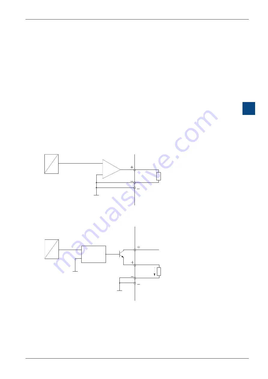
The following connection diagram shows a typical wiring layout for:
●
voltage outputs with the PCD3.W605 and PCD3.W625 modules or
current outputs with the PCD3.W615
Connection for 0...10V (W605) or -10V...+10V (W625):
Connection for 0...20 mA (PCD3.W615):
An external 24 VDC supply is required for current outputs
4 (A2)
D
A
5
U
R
3 k
4 (A2)
D
A
5
I
VOLTAGE
CONTROLLED
CURRENT
SOURCE
+ 24 VDC
R = 0...500
Ω

