Saia-Burgess
Controls Ltd.
Hardware Manual for the PCD3 Series│Document 26/789; Version E 5│31.01.2005
Hardware
PCD3.H110
5-80
5
Programming:
Based on PCD user program (PG5) and pre-pro-
grammed function blocks (FB). For the use with RIOs
other FBs exist. Motion X software supports initializa-
tion of the module and both the numerical and graphi-
cal notation of values.
Terminal:
Pluggable 10-pole cage clamp terminal (4 405 4957 0)
or pluggable 10-pole screw terminal (4 405 4959 0),
both for wires up to 2.5 mm²
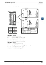
LED’s and connection terminals
Block diagram
For details, please refer to manual 26/755, “PCD2.H110 - Universal counting and
measuring module”
Watchdog: This module cannot be used on the base address 240 because it would
interact with the watchdog, which would cause malfunction.
Please refer to the
“Watchdog”
section for details on how to use the watchdog
correctly together with PCD3 components.
E 0
E 1
E 2
E 3
A 0
A 1
User PROM
Oscillator
FPGA
(Field Programmable
Gate Array)
P
C
D
bu
s
Input filter and adapter 24V to 5V
Output amplifier 5 .to. 32 VDC (Uext)
Input "A"
Input "B"
EnableC
EnableM
CCO
TCO
0
1
2
3
4
5
6
7
LED 0...7 Terminal 0
Description
Label
Address
Label
A
B
EnC
EnM
CCO
TCO
nc
nc
+
–
0
1
2
3
4
5
6
7
8
9
PCD3.H1
10
8 universalI
/Os
A
B
EnC
EnM
CCO
TCO
LEDs
Terminal 9
Terminal
H
1
1
0
i
LED
In/Output
0
A
1
B
2
EnC
3
EnM
4
CCO
5
TCO


