Saia-Burgess
Controls Ltd.
Hardware Manual for the PCD3 Series│Document 26/789; Version E 5│31.01.2005
Hardware
PCD3.H210
5-85
5
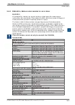
Circuit type:
positive switching
Output delay:
typically 50 μs, max 100 μs at ohmic load
Power supply
Internal current consumption:
(from +5 V bus)
85 mA
Internal current consumption:
(from V+ bus)
0 mA
External current consumption:
for all outputs max. 2A
,
residual ripple max. 10%
Operational conditions
Ambient temperature:
operation 0...+55°C without forced ventilation,
storage -20...+85°C
Interference immunity:
CE mark according to EN 50081-1 and EN 50082-2
Programming:
Based on PCD user program (PG5) and pre-
programmed function blocks (FB). Motion X software
supports initialization of the module and both the
numeric and graphical notation of values.
Terminal:
Pluggable 10-pole cage clamp terminal (4 405 4957 0)
or pluggable 10-pole screw terminal (4 405 4959 0),
both for wires up to 2.5 mm²
*) For more details, please refer to manual 26/760, “PCD2.H210 - Motion control
module for stepper motors”
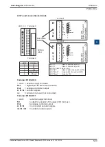
LED’s and connection terminals
LED E0:*) Voltage at input 0: (Emergency stop) LED A0: Voltage at output 0: PUL
LED E1:*) Voltage at input 1: (LS1)
LED A1: Voltage at output 1: DIR
LED E2:*) Voltage at input 2: (REF)
LED A2: Voltage at output 2
LED E3:*) Voltage at input 3: (LS2)
LED A3: Voltage at output 3
*) status inverted when used as limit switch
0
1
2
3
4
5
6
7
LED 0...7 Terminal 0
Description
Label
Address
Label
PCD3.H210
Motion Control for SM
0
1
2
3
4
5
6
7
8
9
E0
E1
E2
E3
PUL
DIR
A2
A3
+
–
E0
E1
E2
E3
PUL
DIR
A2
A3
LEDs
Terminal 9
Terminal
H
2
1
0
LED
In/Output
0
E0
1
E1
2
E2
3
E3
4
A0/PUL
5
A1/DIR
6
A2
7
A2
i


