Hardware Manual for the PCD3 Series│Document 26/789; Version E 5│31.01.2005
Saia-Burgess
Controls Ltd.
Expansion housings
PCD3.Mxxx0 Classic CPUs and expansion housings
3-38
3
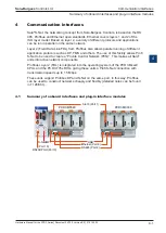
Profibus-DP or Profi-S-Net network line termination resistors
To prevent reflections at the line-ends, every segment must be terminated at the
physical extremity of its line.
This means that the lines are biased at the equilibrium rest potential.
According to the Profibus standard, this must not be done directly on Profibus de-
vices, but must be achieved by means of external components.
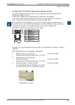
Both the PCD7.T160 termination box and commercially available 9-pole Profibus
D-Sub connectors are suitable for this purpose; for more details, see manual 26/740
“Installation components for RS485 networks” and 26/765 “Profibus-DP”.
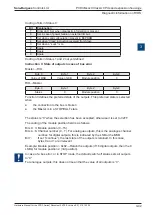
Network termination should therefore be as follows:
1
Shield
3
RxD/TxD-P
4
CNTR-P
5
DP GND
6
DP +5V
8
RxD/TxD-N
9
CNTR-N
Supplier for 9-pole Profibus D-Sub connectors to connect PCD controllers to Profibus
networks:
ERNI Elektrotechnik AG, Brüttisellen, Switzerland:
●
ER
bic
junction, horizontal grey:
Erni Ref. 103648
(junction fitted with series inductance of 110 nH)
●
ER
bic
junction, horizontal grey:
with PG connector:
Erni Ref. 103663
(junction fitted with series inductance of 110 nH)
●
ER
bic
termination, horizontal yellow:
Erni Ref. 103649
(junction fitted with series inductance of 110 nH
plus termination resistors of 390 Ω and 220 Ω)
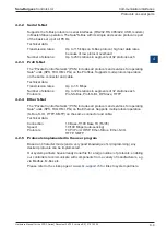
ERNI ER
bic
connector
1
2
3
4
5
6
7
8
9
Frontview
R220
R
39
0
R
39
0
i

