background image

Software update

98-136280-B

Chapter 8:  Service

8-5

8888

Ser

vic

e

8.2

Software update

8.2.1

Hardware and software requirements (updating ADU and ACU)

The following items are required before the software can be updated:

• One computer with a standard Ethernet port available.

• A standard Internet browser.

• 1024×768 pixels or higher display resolution. The program is best viewed using 

small fonts.

• One straight LAN cable.

• The file containing the new software.

8.2.2

Software update (ADU and ACU)

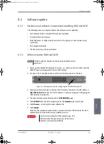
1. Power up the SAILOR 100 Satellite TV system, i.e. switch on the ACU. Wait until the 

SAILOR logo has disappeared from the ACU display.

2. Connect a PC to the LAN interface at the front LAN connector of the ACU.


3. Open your Internet browser and enter the IP address of the ACU. The IP address is 

http://192.168.0.1

 (default). For further details on network setup see 

Configuring the 

LAN network

 on page 6-24.

4. The web interface opens directly with the 

DASHBOARD

 page. 

5. Click 

SERVICE

 from the left navigation pane. The 

Upload 

page is displayed.

6. Click 

Browse... 

and locate the new software file.

7. Click 

Upload

.

Note that the upload procedure takes a couple of minutes. When done, the ACU 
automatically restarts with the new software version.

Note

Software update should only be done by qualified service 
personnel.

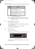
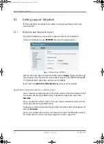
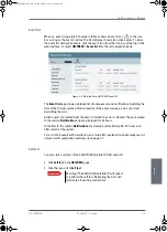
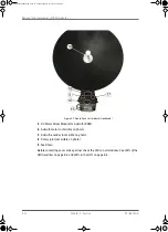
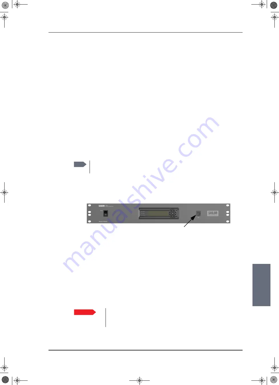
Figure 8-3: LAN connector used for configuring the SAILOR 100 Satellite TV

Important

Do not browse away from the upload page. This 
will terminate the upload process. Wait for the 
browser to reload automatically.

SAILOR100IM.book  Page 5  Friday, January 18, 2013  10:28 AM

Summary of Contents for 100

Page 1: ...INSTALLATION MANUAL SAILOR 100 Satellite TV ...

Page 2: ......

Page 3: ...SAILOR 100 Satellite TV Installation manual Document number 98 136280 B Release date 18 January 2013 SAILOR100IM book Page i Friday January 18 2013 10 28 AM ...

Page 4: ... registered trademark of Thrane Thrane A S in the European Union and the United States Windows is a registered trademark of Microsoft Corporation in the United States and other countries Other product and company names mentioned in this manual may be trademarks or trade names of their respective owners GPL notification The software included in this product contains copyrighted software that is lic...

Page 5: ...e performed by a technician authorized by Thrane Thrane A S Grounding cables and connections To minimize shock hazard and to protect against lightning the equipment chassis and cabinet must be connected to an electrical ground The ACU must be grounded to the ship For further grounding information refer to the Installation manual Do not extend the cables beyond the lengths specified for the equipme...

Page 6: ...maintenance personnel Do not replace components with the power cable connected Under certain conditions dangerous voltages may exist even with the power cable removed To avoid injuries always disconnect power and discharge circuits before touching them Failure to comply with the rules above will void the warranty SAILOR100IM book Page iv Friday January 18 2013 10 28 AM ...

Page 7: ...2 1 2 1 1 3 3 2 3 5 4 2 6 3 3 6 3 6 6 3 10 6 4 6 5 1 The following figures have been added 2 5 6 32 The following figures have been edited 2 3 2 7 3 25 6 2 6 3 6 4 6 6 6 7 6 9 6 22 6 24 6 30 6 34 6 35 6 36 8 2 The following tables have been added 6 8 The following tables have been edited 1 1 2 1 2 2 4 3 6 1 6 2 6 5 C 1 C 2 18 January 2013 UFO SAILOR100IM book Page v Friday January 18 2013 10 28 AM...

Page 8: ...vi 98 136280 B SAILOR100IM book Page vi Friday January 18 2013 10 28 AM ...

Page 9: ... 2 1 2 1 1 Above Deck Unit ADU 2 3 2 1 2 Antenna Control Unit ACU 2 7 2 1 3 Control Panel for setup and operation 2 9 2 1 4 Multiswitch optional 2 9 2 1 5 SAILOR Transmodulator optional 2 9 2 1 6 Power supply optional 2 10 2 1 7 System configuration example 2 10 2 2 Part numbers and options 2 11 2 2 1 Applicable Thrane Thrane model and part numbers 2 11 2 2 2 Options for SAILOR 100 Satellite TV 2 ...

Page 10: ...2 4 Ship motion and offset from the ship s motion centre 3 6 3 2 5 ADU mast design Foundation and height 3 7 3 2 6 Interference 3 12 3 2 7 Other precautions 3 15 3 3 Installation of the ADU 3 16 3 3 1 Installing the ADU 3 17 3 3 2 Opening and removing the service hatch 3 20 3 3 3 Grounding the ADU 3 21 3 3 4 Alternative ADU cable 3 22 3 4 Installation of the ACU 3 22 3 4 1 Installing the ACU 3 22 ...

Page 11: ...s of the Control Panel 4 6 4 3 Interfaces of the SAILOR Transmodulator optional 4 6 Chapter 5 Connecting power 5 1 Power source 5 1 5 2 Power cable selection 5 2 5 2 1 Source impedance 5 2 5 2 2 Measuring the ship source impedance 5 2 5 2 3 Power cable recommendations 5 3 5 3 Connecting power 5 4 5 4 Power up 5 5 Chapter 6 Configuration 6 1 Introduction to the configuration tools 6 1 6 1 1 Overvie...

Page 12: ...the Control Panel 6 37 6 4 1 Getting started 6 37 6 4 2 Creating or editing a profile 6 38 6 4 3 Selecting the active profile 6 41 6 4 4 Deleting a profile 6 41 6 4 5 Event list 6 42 6 4 6 Help 6 42 6 4 7 About 6 43 6 5 Keypad and menus of the ACU 6 44 6 5 1 ACU display and keypad 6 44 6 5 2 Navigating the menus 6 45 6 5 3 The menu tree 6 45 6 5 4 Adjusting brightness of the display 6 48 6 5 5 Res...

Page 13: ...eshooting 8 13 8 6 1 Overview 8 13 8 6 2 Event list for troubleshooting 8 13 8 6 3 Diagnostic report for troubleshooting 8 13 Appendix A Technical specifications A 1 SAILOR 100 Satellite TV system components A 1 A 1 1 General specifications A 1 A 1 2 ADU A 2 A 1 3 ACU A 4 A 1 4 Control Panel and SAILOR Transmodulator A 4 A 2 Outline drawings A 5 A 2 1 ADU A 5 A 2 2 ACU A 6 A 2 3 N connector interf...

Page 14: ... Grounding the ACU B 8 B 5 2 Grounding the ADU B 8 B 6 Separate ground cable B 9 B 6 1 Ground cable construction B 9 B 6 2 Ground cable connection B 10 B 6 3 Isolation of the ADU from the mounting base B 10 B 7 Jumper cable for grounding B 12 B 8 RF interference B 13 B 8 1 Recommendations B 13 Appendix C System messages C 1 Event messages overview C 1 C 2 List of ADU events C 2 C 3 List of ACU eve...

Page 15: ...st flange top and side view 3 7 Figure 3 6 ADU mast flange recommended flatness on the mast mount plateau 3 7 Figure 3 7 ADU mast flange distance to the welded seam 3 8 Figure 3 8 ADU bottom view 3 8 Figure 3 9 Free mast length and bracing for a tall mast 3 9 Figure 3 10 Interference with the vessel s radar 3 12 Figure 3 11 Recommended distance to transmitters m for frequencies below 1000 MHz 3 14...

Page 16: ... 6 12 Figure 6 7 Web interface SETTINGS list of satellite profiles example 6 14 Figure 6 8 Web interface SETTINGS Satellite profiles new entry example 6 14 Figure 6 9 TV satellite remove and disable 6 16 Figure 6 10 Web interface SERVICE TV satellites example 6 17 Figure 6 11 Web interface SETTINGS TV satellites new entry example 6 17 Figure 6 12 Reference satellite remove and disable 6 18 Figure ...

Page 17: ...ample and keypad of the ACU 6 44 Figure 6 36 ACU menu tree 6 45 Figure 6 37 Reset the system 6 48 Chapter 7 Installation check Chapter 8 Service Figure 8 1 Web interface HELPDESK 8 2 Figure 8 2 Web interface HELPDESK Event list 8 3 Figure 8 3 LAN connector used for configuring the SAILOR 100 Satellite TV 8 5 Figure 8 4 Verifying software update 8 6 Figure 8 5 LEDs on the ACU 8 8 Figure 8 6 ADU mod...

Page 18: ...d cable B 9 Figure B 7 Isolation of the ADU from the mounting base B 10 Figure B 8 ADU isolation and grounding cable B 11 Figure B 9 Jumper cable for grounding specifications B 12 App C System messages SAILOR100IM book Page xvi Friday January 18 2013 10 28 AM ...

Page 19: ...4 Interfaces Table 4 1 DC Input plug outline and pin assignment 4 2 Table 4 2 N connector outline and pin assignment 4 3 Table 4 3 F connector Rx outline and pin assignment 4 3 Table 4 4 NMEA 0183 2000 connector outline and pin assignment 4 4 Table 4 5 Ethernet connector outline and pin assignment 4 5 Chapter 5 Connecting power Chapter 6 Configuration Table 6 1 Configuration tools Web interface an...

Page 20: ... connectors and wiring 7 3 Table 7 3 Installation check list Control Panel connectors and wiring 7 4 Table 7 4 Installation check list Functional test in harbour 7 5 Chapter 8 Service Table 8 1 LEDs of the ADU modules 8 8 Table 8 2 LEDs on the ACU 8 8 App A Technical specifications Table A 1 General specifications A 1 Table A 2 Technical specifications for the Above Deck Unit A 2 Table A 3 Technic...

Page 21: ...cording to the guidelines in this manual For daily use of the SAILOR 100 Satellite TV system see the SAILOR 100 Satellite TV User manual 1 2 Manual overview This manual has the following chapters Introduction Installation Interfaces Connecting power Configuration Installation check Service This manual has the following appendices Technical specifications Grounding and RF protection System messages...

Page 22: ...Select SETTINGS LAN Italic is used to emphasize the paragraph title in cross references Example For further information see Connecting Cables on page Document number Title 98 136311 SAILOR 100 Satellite TV User manual 98 136644 SAILOR 6004 Control Panel Installation manual 98 130088 Control Panel Installation manual TT 6007A Message Terminal 98 136455 SAILOR Transmodulator Installation manual Tabl...

Page 23: ...amage on equipment or personal safety General precautions All personnel who operate equipment or do maintenance as specified in this manual must know and follow the safety precautions The warnings and cautions that follow apply to all parts of this manual WARNING Before using any material refer to the manufacturers material safety data sheets for safety information Some materials can be dangerous ...

Page 24: ...Precautions 1 4 Chapter 1 About this manual 98 136280 B SAILOR100IM book Page 4 Friday January 18 2013 10 28 AM ...

Page 25: ...ntrol Unit The programmable LNB makes the system truly global and independent of channel providers The single antenna cable 50 ohm carries DC control and TV bands between the ADU and ACU The radome does not have to be removed neither before nor after the installation To protect the Above Deck Unit the built in DC motors act as breaks during transport and when the Above Deck Unit is not powered The...

Page 26: ...outputs 4 2 TV bands output simultaneously VL HL VH HH for linear setting of polariser or LHCP RHCP for circular mode setting of polariser Programmable LNB LO frequencies No scheduled maintenance Tracking of any Ku band satellite Low audible noise emission from ADU Support for optional TV distribution system i e SAILOR Transmodulator Remote control from another network entity e g a Control Panel F...

Page 27: ...ntenna consisting of a suspended antenna with a standard global RF configuration The ADU s weight is 126 kg It is stabilized by heavy duty vibration dampers in 3 axis plus skew and can be used in environments with elevations of 25 to 125 The ADU is powered by the ACU and protected by a radome Figure 2 2 Above Deck Unit ADU SAILOR100IM book Page 3 Friday January 18 2013 10 28 AM ...

Page 28: ...e Module TIM 3 DC Motor Driver Module for cross elevation DDM 4 Cross elevation motor and encoder 5 Zero Reference Module 3 pcs 2 in Figure 2 3 1 in Figure 2 4 ZRM not visible on photo 6 DC Motor Driver Module for elevation 7 Elevation motor and encoder on the side Figure 2 3 ADU modules 1 2 SAILOR100IM book Page 4 Friday January 18 2013 10 28 AM ...

Page 29: ...ixed position 13 Pedestal Control Module PCM 14 Service switch In switch off position the DC Motor Driver modules are turned off for safe conditions during service and repair The switch must be in on position for normal ADU operation 15 DC Motor Driver Module for Azimuth DDM 16 Azimuth motor not visible on photo 17 Azimuth encoder not visible on photo 18 Rotary joint not visible on photo 19 Feed h...

Page 30: ...quencies This feature makes the system truly global and independent of channel providers For further information how to select the appropriate LNB LO frequencies see Satellite profiles New entry and Edit on page 6 14 and Creating or editing a profile on page 6 38 Installation friendly Four lifting brackets included in the delivery and reuse of packing material help getting the ADU safely into plac...

Page 31: ...tors and logs information for all modules The ADU performs a POST Power On Self Test and you can request a self test PAST Person Activated Self Test and Continuous Monitoring CM Error codes can be read out in the web interface the Control Panel and in the display of the ACU ADU software is updated automatically when making a software update of the ACU 2 1 2 Antenna Control Unit ACU The ACU is the ...

Page 32: ... the front Power connector On Off power switch Service friendly You can do remote diagnostics and service with the ACU Its built in test equipment checks constantly the ACU s modules for proper functioning it monitors and logs for all modules It performs POST Power On Self Test and you can request a PAST Person Activated Self Test Continuous Monitoring CM is also available BITE error codes can be ...

Page 33: ... system status information If the optional SAILOR Transmodulator is connected to the ACU the Control Panel can also be used to read out status of the SAILOR Transmodulator and handle and configure TV program packages for each satellite profile 2 1 4 Multiswitch optional A Multiswitch is required if one or several satellite receivers are used in the network With a Multiswitch connected to the ACU a...

Page 34: ...e the SAILOR 6080 AC DC Power Supply to provide DC power to the SAILOR 100 Satellite TV 2 1 7 System configuration example The following figure shows system configuration examples with a SAILOR 100 Satellite TV and a SAILOR Transmodulator Figure 2 8 SAILOR Transmodulator optional Figure 2 9 ADU ACU Control Panel and SAILOR Transmodulator optional ADU ACU Control Panel SAILOR Transmodulator SAILOR1...

Page 35: ... inch rack 406004A TT 6004 SAILOR 6004 Control Panel Table 2 1 Model and part numbers for the SAILOR 100 Satellite TV system T T units Part number Description 406080A 00500 SAILOR 6080 AC DC Power Supply 407090A 950 Antenna cable 50 m for 407390A 407090A 925 Pigtail Cable 1 25 m N Conn female male 401841A 00500 5x5 IF Amplifier 401842A 00500 Multiswitch 5x8 401843A 00500 Multiswitch 5x12 401844A 0...

Page 36: ...Part numbers and options 2 12 Chapter 2 Introduction 98 136280 B SAILOR100IM book Page 12 Friday January 18 2013 10 28 AM ...

Page 37: ...in the box ADU Unpack your SAILOR 100 Satellite TV ADU and check that the following items are present ADU with 4 lifting brackets already mounted Package with bolts washers and cable glands 2 sizes ACU Unpack your SAILOR 100 Satellite TV ACU and check that the following items are present 1 x Ethernet cable 2 m Power connector NMEA multi connector Installation manual this manual User manual SAILOR1...

Page 38: ...inspect it thoroughly for hidden damage and loose components or fittings If the contents are incomplete if there is mechanical damage or defect or if the system does not work properly notify your dealer 3 1 4 Tools needed Unbraco key 5 mm included mounted on a tool holder inside the radome Other tools that may be needed during the installation Torx TX20 to open the locks of the service hatch Wrenc...

Page 39: ...ther precautions 3 2 1 General site considerations For optimum system performance some guidelines on where to install or mount the different components of the SAILOR 100 Satellite TV System must be followed It is recommended to mount the ADU in a location with as much 360 free line of sight to the satellite as possible while making sure that the support structure fulfills the requirements for the ...

Page 40: ... obstruction elevate the ADU by mounting it on a mast or on a mounting pedestal on a deck or deck house top The ADU is stabilized in 3 axis plus skew and can be used in environments with elevations of 25 to 125 to allow for continuous pointing even in heavy sea conditions Any obstructions such as masts funnels bridge house etc within this field can cause signal degradation or signal loss Figure 3 ...

Page 41: ... 8 blocking zones Each blocking zone is set up with azimuth start and stop and elevation angle The blocking zones are set up in the SAILOR 100 Satellite TV built in web interface of the ACU For further information see Setting up Blocking zones on page 6 21 Figure 3 2 2 blocking zones azimuth example Figure 3 3 Blocking zone elevation angle example QWHQQD 2EVWUXF WLRQ LPXWK LPXWK LPXWK LPXWK ORFNLQ...

Page 42: ...ship see Table 3 1 If the g force applied is too high performance and ADU signal stabilization may be reduced and eventually the ADU may be damaged Refer to the following table for allowed mounting heights above the ship s motion centre Figure 3 4 Maximum distance from the ship s motion centre h max Min roll period Max ADU mounting height h max Full performance Potential risk of damage 4 s 12 m 16...

Page 43: ...he top of the ADU mast with a flange with clearance holes matching the bushings in the radome and with minimum 4 gusset plates No center hole is necessary in the flange Flange thickness Minimum 15 mm 4 gusset plates Minimum 15 mm thick must be placed close to the holes in the mounting plate and evenly distributed Recommended flatness on the mast mount plateau is below 3 0 mm Figure 3 5 ADU mast fl...

Page 44: ...flange distance to the welded seam CAUTION Avoid sharp edges where the flange is in direct contact with the radome Round all edges as much as possible to avoid damaging the surface of the radome Figure 3 8 ADU bottom view SAILOR100IM book Page 8 Friday January 18 2013 10 28 AM ...

Page 45: ...recommended to shorten the mast length as much as possible to obtain higher frequencies Preferably mount stays or wires to stabilize the mast further The tables in the next sections give some suggested design values for the free mast length Figure 3 9 Free mast length and bracing for a tall mast Note Make sure that there is free space below the drain tube Read also Condensation and water intrusion...

Page 46: ...mm Wall Thickness mm Weight kg m 0 4a a The height of 0 4 m is not recommended to be used as it will make access through the ADU s service hatch difficult 200 5 24 0 0 6 220 5 26 5 0 8 250 5 30 2 1 270 5 32 7 Table 3 2 Mast dimensions without braces Mast with 3 braces Max free mast length steel m Outer Diameter mm Wall Thickness mm Outer Diameter for brace mm Thickness for brace mm 1 2 140 10 50 5...

Page 47: ... m Outer Diameter mm Wall Thickness mm Outer Diameter for brace mm Thickness for brace mm 1 2 160 10 80 5 0 1 2 200 5 80 5 0 1 6 180 10 80 5 0 1 6 220 5 80 5 0 2 180 10 80 5 0 2 240 5 80 5 0 2 5 200 10 80 5 0 2 5 260 5 80 5 0 Table 3 4 Mast dimensions with 2 braces SAILOR100IM book Page 11 Friday January 18 2013 10 28 AM ...

Page 48: ...a few degrees and a vertical beam width of up to 15 the worst interference can be avoided by mounting the ADU at a different level meaning that the ADU is installed minimum 15 above or below the radar antenna Due to near field effects the benefit of this vertical separation could be reduced at short distances between radar antenna and the SAILOR 100 Satellite TV ADU Therefore it is recommended to ...

Page 49: ...Even at distances greater than d min in the previous section the radar might still be able to degrade the performance of the SAILOR 100 Satellite TV system The presence of one or more S or X band radars within a radius up to 100 m may cause a minor degradation of the Ku band reception The degradation will be most significant at high radar pulse repetition rates X band 3 cm 10 GHz damage distance R...

Page 50: ...isted in the previous section are applied It is strongly recommended that interference free operation is verified experimentally before the installation is finalized GPS receivers Good quality GPS receivers will work properly very close to the ADU Other transmitters See the following figure for minimum recommended distance to transmitters in the frequency range below 1000 MHz CAUTION The ADU must ...

Page 51: ...sure the ADU s drain tube is open and that there it free space between the drain tube and the mounting surface so water can escape and there is ventilation for the ADU It is recommended not to use pneumatic tools for cleaning the radome especially at a short distance and directly at the split between top and bottom Deposits Do not place the ADU close to a funnel as smoke deposits are corrosive Fur...

Page 52: ...NING Use a strong webbed sling with a belt to lift the ADU without damaging the radome Make sure that the sling can carry the ADU s weight 126 kg 278 lbs WARNING The ADU may be subject to swaying motions in windy conditions Always use tag lines to stabilise the ADU during hoisting Figure 3 13 Use of strong sling with a belt and tag lines for safe hoisting Webbed sling with belt Tag lines SAILOR100...

Page 53: ...intain vertical orientation of the ADU center line Consider the aspect of interference read more about this in ADU mast design Foundation and height on page 3 7 Install the ADU where vibrations are limited to a minimum Always use all 4 bolts when installing the ADU To install the ADU do as follows 1 Install the mast with the mast flange and have the 4 M12 bolts ready 2 Undo all shipping buckles ta...

Page 54: ... Install the ADU on the mast flange with 4 M12 bolts and washers Read carefully and follow instructions given in Grounding the ADU on page B 3 Tightening torque value 30 Nm 8 Put the coaxial ADU cable through the protection plate as shown in the following figure and connect the N connector of the ADU cable to the ADU Figure 3 15 ADU installation webbed sling attached to the 4 lifting brackets Figu...

Page 55: ...y is properly protected against seawater and corrosion As a minimum wrap it with self amalgamating rubber 9 Put the protection plate in place and fasten the 4 bolts picture 5 10 Fasten the nut picture 6 Where the cables are exposed to mechanical wear on deck through bulkheads etc protect the cables with steel pipes Otherwise follow standard procedures for cabling in ship installations Figure 3 17 ...

Page 56: ...in the latches with a Torx TX20 screw driver to protect the ADU modules against unauthorised access You can remove the hatch for better mobility when servicing the antenna Do as follows to open and remove the service hatch 1 With a Torx TX20 screw driver remove the two screws locking the latches 2 Pull open the two latches and let the lid fall open 3 Remove the 2 split pins and park them 4 Pull th...

Page 57: ...nding for fibre glass hulls on page B 8 To obtain a good ground connection the metal underneath the head of at least one bolt must be clean of insulating protective coating and a serrated washer should be used After tightening the bolts we recommend that you seal the area suitably in order to avoid corrosion of the grounding point Use stainless steel bolts and washers Optimum grounding is achieved...

Page 58: ... the ACU A cable relief bracket is already mounted when receiving the ACU The cable relief is a simple system to secure cables with cable strips It offers a number of holders to which you can secure the cables from the ACU To install the 19 rack version of the ACU do as follows 1 Slide the ACU into a 1 5U space in a 19 rack 2 Mount the screws in each side through the holes in the front and fasten ...

Page 59: ...ure that the grounding requirements are met See the appendix Grounding and RF protection on page B 1 for details about grounding ADU cable The ADU is connected to the ACU with the ADU cable coax cable with an N connector at both ends For information on ADU grounding see Grounding the ADU on page 3 21 At the ACU end it is strongly recommended to ground the ADU cable Use a short cable from the ACU t...

Page 60: ... Control Panel see the table List of Related Documents on page 1 2 To connect the Control Panel to the ACU do as shown below 1 Connect an Ethernet cable to the Ethernet connector at the back of the Control Panel 2 Connect the other end of the Ethernet to LAN 4 of the ACU rear connector panel possibly through a switched network Figure 3 23 ACU ground stud Figure 3 24 Connecting the Control Panel to...

Page 61: ...faces of the SAILOR 100 Satellite TV ACU 4 1 1 LEDs display and keypad 4 1 2 Connector panel overview Figure 4 1 ACU LEDs display and keypad Figure 4 2 ACU connector panels overview NMEA reserved reserved LAN 1 Power On Off LAN 2 LAN 3 LAN 4 Service port TV output Set to On ADU V Cable to front LAN connector Low H Low V High H High RX DC out Cables to internal connector Ground Set to On SAILOR100I...

Page 62: ...or wires up to AWG10 6 mm2 The connector for DC input is included in the delivery Insert the power cable as shown below and plug in the connector Use the two red clamps to fasten the connector For more information about power supply and power requirements see Connecting power on page 5 1 Important Set the On Off switch at the back of the ACU to On Then you can use the On Off switch at the front pa...

Page 63: ...CP is delivered on the vertical ports VL and VH and LHCP is delivered on the horizontal ports HL and HH 4 1 7 DC output connector Connector for internal use cable already connected Outline on the ACU Conductor Pin function Inner DC to ADU ACU to ADU internal communication Rx 950 5450 MHz Outer GND Shield Table 4 2 N connector outline and pin assignment Important Do not use TNC connectors on the AD...

Page 64: ...etected by the ACU the user cannot configure this interface Supported NMEA string 1 HEHDT North seeking Gyro compass 2 GPHDT GPS compass 3 HNHDT Non North seeking gyro compass 4 IIHDT Integrated Instrument 5 HCHDT Magnetic compass Outline on the ACU Pin number Pin function Wire color 1 Not connected 2 NET H NMEA 2000 White 3 NET L NMEA 2000 Blue 4 NET S NMEA 2000 Red 5 NET C NMEA 2000 Black 6 Not ...

Page 65: ...re use 4 1 10 LAN1 LAN2 LAN3 and LAN4 connectors Four Ethernet connectors type RJ45 for PC laptops routers wireless access points The maximum cable length per connection is 100 m For information how to configure the LAN network see Configuring the LAN network on page 6 24 Cable type CAT5 shielded Outline Pin number Pin function Wire color 1 Tx White orange 2 Tx Orange 3 Rx White green 4 Not connec...

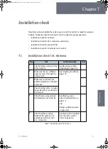
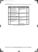
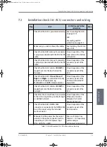
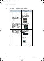
Page 66: ...rol Panel For a description of the interfaces see the installation manual of the Control Panel 4 3 Interfaces of the SAILOR Transmodulator optional For a description of the interfaces see the installation manual of the SAILOR Transmodulator SAILOR100IM book Page 6 Friday January 18 2013 10 28 AM ...

Page 67: ...r the power supply The 24 VDC ship supply provides power for the ACU An AC line provides power through an AC DC power supply The TT 6080A Power Supply is recommended In order to protect against short circuit in the power cable connector the ship s DC outlet must be protected by a 30 A fuse or circuit breaker Note Be aware of high start up peak current 35 A at 24 VDC 5 ms SAILOR100IM book Page 1 Fr...

Page 68: ... selection see Power cable recommendations on page 5 3 5 2 2 Measuring the ship source impedance Select a power outlet from the ship 24 VDC system and measure the source impedance of the ship installation as described below 1 Measure the voltage without load R var disconnected 2 Set the current to e g 1 A by adjusting R var 3 Measure the corresponding voltage change Example 1 A and 50 mV Source im...

Page 69: ... Rmaxfor SAILOR 100 Satellite TV with SAILOR Transmodulator and max 90 mOhm Rmax for SAILOR 100 Satellite TV without SAILOR Transmodulator including the source impedance in the ship installation Rsource The total impedance is made up of the following Source impedance in the ship installation Impedance of the selected power cable To calculate the maximum cable extension do as follows 1 First measur...

Page 70: ...hm m 6 2 m AWG10max 0 5 x 60 mOhm 0 3 8 mOhm m 7 9 m 5 3 Connecting power To connect the power cable to the ACU 1 Connect the positive and negative input terminals to the ship s DC supply according to the recommendations in the previous sections 2 Connect the power plug to DC Input For information on pin out see DC Input connector on page 4 2 Maximum length 0 5 Rmax Rsource Rwire Figure 5 2 Connec...

Page 71: ...see Status signalling with LEDs and status messages on page 8 7 Make sure there are no hardware failures or error codes present check the display of the ACU for events For more information on error codes and events see Troubleshooting on page 8 13 and System messages on page C 1 4 Continue to get the SAILOR 100 Satellite TV system operational do the following Make an azimuth calibration Configure ...

Page 72: ... Initializing ADU SW upload If the software versions in the ADU and ACU are not the same a software update is done during startup ADU POST READY POINTING ANTENNA ACQUIRING SIGNAL FREQUENCY SCANNING TRACKING SAILOR 100 Satellite TV operational When the display shows TRACKING and the LED TV Ready is steady green the system is operational SAILOR100IM book Page 6 Friday January 18 2013 10 28 AM ...

Page 73: ... Overview Use the following tools to configure the SAILOR 100 Satellite TV system For quick start instructions see Calibration of the SAILOR 100 Satellite TV on page 6 4 Configuration tool When used PC with Internet browser and built in web interface of the ACU Installation and service Control Panel Daily use Table 6 1 Configuration tools Web interface and Control Panel Note For information on dai...

Page 74: ...e configured Power LED Green TV Ready LED Off Fail Pass LED Flashing green during power on self test after that steady green 2 Connect a PC to LAN interface 3 Service port standard Ethernet of the ACU or to the front LAN connector of the ACU 3 Open your Internet browser and enter the IP address of the ACU The IP address is http 192 168 0 1 default 4 The web interface opens directly with the DASHBO...

Page 75: ...d introduction to the web interface see Overview and navigation on page 6 8 If you want to use another LAN port you must configure it according to your network requirements For information how to configure the LAN connectors see Configuring the LAN network on page 6 24 6 1 3 Connecting the Control Panel The Control Panel is typically connected during installation For further information see Instal...

Page 76: ...ection to the bow to stern line of the ship This procedure is fully automatic For a detailed introduction to the web interface see Overview and navigation on page 6 8 6 2 1 Heading and calibration of azimuth Access the page for heading and calibration through SERVICE Calibration Important You must logon as an administrator to do a calibration See Administration on page 6 32 Figure 6 3 Web interfac...

Page 77: ...ng settings you must make an azimuth calibration afterwards Note The ship must not move during the calibration procedure Important It is strongly recommended to use the reference satellites in the drop down list instead of manual input It is difficult to manually supply information that is unique and will not possibly match a different satellite than expected Hence when manually supplying the data...

Page 78: ...o verify the correctness or precision of the supplied longitude It is therefore important to supply the correct longitude including the first decimal Satellite identifier NID value Description NID 0 Satellite identifier is not used NID 1 65535 Supplied NID is matched against Network ID broadcast by the satellite Orbital position n a Supplied longitude is matched with orbital position broadcast by ...

Page 79: ...fective hardware 5 The antenna could not point with sufficient precision Check that the antenna is mounted in a stable way Other possible causes might be electrical or mechanical faults 6 No signal received Check that there is free line of sight Try again or try with another satellite 7 RF setup error 8 Invalid satellite e g satellite not visible Error code Explanation Table 6 3 Possible error cod...

Page 80: ...w and navigation Topics in the web interface Use the site map to get an overview over the existing menus submenus and topics You can click on each menu in the site map to go directly to the page or display the respective submenu Figure 6 4 Topics in the web interface SITE MAP SAILOR100IM book Page 8 Friday January 18 2013 10 28 AM ...

Page 81: ...us field shows the signal strength The signal strength can vary during operation depending on the current position relative to the satellite 3 The icon bar shows icons for active events when relevant For explanations of the icons see the next section Icons in the icon bar 4 The contents section shows the page selected in the navigation pane This section is used for viewing or changing settings or ...

Page 82: ...abling of the Proxy server settings for one specific IP address so you can disable Proxy server settings for the web interface only if you wish Consult your browser help for information To disable the use of a Proxy server completely do as follows 1 In Microsoft Internet Explorer select Tools Internet Options Connections LAN Settings Icon Explanation An event is active Click the icon to see a list...

Page 83: ...the ACU see Connecting to the web interface on page 6 2 If you want to use another LAN port than LAN 3 you must configure it according to your network requirements For information how to configure the 4 LAN connectors see Configuring the LAN network on page 6 24 6 3 2 Using the Dashboard The Dashboard is the first screen that is displayed when the user or administrator enters the IP address of the...

Page 84: ...s the current satellite Frequency scanning scanning for transponders Blocking zone antenna is pointing into a blocking zone Service switch service switch in ADU activated Safe mode error followed by an error description GPS position Current position of the vessel reported by the GPS module Vessel heading Ship s heading in degrees with reference to North provided by the ship s gyro Satellite profil...

Page 85: ...n the satellite profile ACU part name ADU part name ACU serial number ADU serial number Software version Part names serial numbers for ACU and ADU software version of the SAILOR 100 Satellite TV POINTING parameter Description Azimuth relative Current value for azimuth relative to the vessel heading Elevation relative Current value for elevation relative to the vessel Polarisation skew Current valu...

Page 86: ... necessary for a successful reception from the satellite You must activate one satellite profile Satellite profiles New entry and Edit To add or edit a satellite profile do as follows 1 Go to SETTINGS or Satellite profiles and click Edit or New entry Figure 6 7 Web interface SETTINGS list of satellite profiles example Figure 6 8 Web interface SETTINGS Satellite profiles new entry example SAILOR100...

Page 87: ...362 GHz Symbol rate Mega symbols per second e g 27 500 MS s Note It is helpful to assign a name containing the location where the Satellite profile is to be used e g Gulf of Mexico or North Sea and possibly the provider Note At some longitudes multiple satellites are co located In this case it is not important which satellite is chosen as long as the longitude is correct The chosen satellite will ...

Page 88: ...ally the data describing a satellite does not change during the lifetime of that satellite and the data will typically not need to be updated It is however possible to manually edit the data or e g add a new entry in case a new satellite has been launched and TV reception is required from the satellite Removing and disabling entries in the list of TV satellites You can only delete user defined ent...

Page 89: ...arisation skew and Max inclination of the satellite For satellite data see documentation from your service provider or from online databases e g www lyngsat com or www satbeams com 4 Click Apply to save the data Figure 6 10 Web interface SERVICE TV satellites example Figure 6 11 Web interface SETTINGS TV satellites new entry example Note For For best performance the longitude of the satellites sho...

Page 90: ...obe Removing and disabling entries You can only delete user defined entries Pre installed entries can be disabled if they are not needed Important Do not add satellites that are solely intended for azimuth calibration If you cannot use any of the pre installed Reference satellites for azimuth calibration you can manually supply the data directly on the page SERVICE Calibration see Heading and cali...

Page 91: ...entry The new user defined entry includes the changes made The pre installed entry remains unchanged and disabled To add or edit a reference satellite do as follows 1 Go to SERVICE Reference satellites and click New satellite or Edit next to an existing entry Figure 6 13 Web interface SERVICE Reference satellites example Figure 6 14 Web interface SETTINGS Satellites new entry example SAILOR100IM b...

Page 92: ...ply to save the settings for the reference satellite 6 3 6 Azimuth adjustment Purpose Azimuth adjustment compensates for minor drift in the heading data received from the ship s compass If enabled the azimuth adjustment is performed immediately before starting acquiring the signal from the satellite selected in the satellite profile Azimuth adjustment may slightly increase acquisition time but wil...

Page 93: ... to re acquire the signal from the TV Satellite The system will ensure that brief blocking of the signal will not deem the signal as lost The database with the reference satellites contains information about which reference satellites to use at given positions Currently there is a maximum of three satellites for any given position This means that the Azimuth Adjustment procedure attempts acquisiti...

Page 94: ... 98 136280 B To define and set a blocking zone do as follows 1 Select SETTINGS Blocking zones 2 Select Active to enable the blocking zone Figure 6 16 Web interface SETTINGS Blocking zones azimuth and elevation SAILOR100IM book Page 22 Friday January 18 2013 10 28 AM ...

Page 95: ... and stop elevation angle for the blocking zone If you enter nothing there will be no blocking zone Values allowed 30 to 90 degrees 5 Click Apply to save the blocking zones Figure 6 17 Blocking zone example 315 45 degrees Figure 6 18 Blocking zone example 45 315 degrees Important You must enter 2 different elevation angles to have an active blocking zone QWHQQD ORFNLQJ RQH QWHQQD ORFNLQJ RQH SAILO...

Page 96: ... Internet connection The ACU has four 10 100 Mbit Ethernet ports labelled LAN port 1 2 3 and 4 The ports are divided in three groups each group operating in its own network You can setup DNS and Gateway To configure the LAN network go to SETTINGS Network Figure 6 19 Web interface SETTINGS Network default settings Important Make sure that the 3 networks do not use IP address ranges that overlap SAI...

Page 97: ...n e mail reports The default host name is acu You can change the name Letters a z digits 0 9 and hyphen are allowed as legal characters Note The host name must start with a letter LAN Port 1 2 LAN port 1 and 2 are switched i e they share the same IP address and operate on the same network LAN port 1 is intended for connecting the SAILOR Transmodulator optional LAN port 1 can be set to static IP de...

Page 98: ...ith network units outside the specified sub nets you must specify a default gateway typically a router The default gateway can be set as a static IP address Then set the default gateway source to static and enter the IP address of the default gateway To remove the default gateway set it to 0 0 0 0 Alternatively if your DHCP server is able to provide a default gateway address and you have selected ...

Page 99: ...cific data To configure the e mail setup do the following 1 Go to SETTINGS E mail setup 2 Enter the data for Outgoing mail server SMTP SMTP port number SMTP authentication User name and password This data is typically provided by your IT department Figure 6 20 Web interface SETTINGS E mail setup example Note You must set Outgoing mail server to an IP address if DNS has not been set up in DNS setup...

Page 100: ...p sending a statistics report do as follows 1 Configure e mail first see E mail setup on page 6 27 2 Go to SETTINGS Reports 3 In the section STATISTICS REPORT enter the following Email sender Email recipients comma separated Send interval Select disabled day default with 2 minute samples week with hourly samples or month with hourly samples The report contains statistics data for the selected inte...

Page 101: ...ng Samp degree Heading Max degree Heading Min degree Heading Range degree Ship s heading sample maximum and minimum value range for the sampling interval See Figure 6 22 Statistics how to read data for a range Antenna Azi degree Antenna Azi Max degree Antenna Azi Min degree Antenna Azi Range degree Current antenna azimuth sample maximum and minimum value range for the sampling interval See Figure ...

Page 102: ... the text file The file name contains the identification of the system example adu acu3_stat_20111021110901_day csv 2 Open the spreadsheet application for example Microsoft Excel On the tab Data click the tab Import from text Import the unzipped text file and follow the instructions in the wizard When asked about the delimiter select comma The following figure shows an example of a statistics repo...

Page 103: ...e section DIAGNOSTICS REPORT enter the following Email sender Email recipients comma separated Send interval Select disabled day default with 2 minute samples week with hourly samples or month with hourly samples The report contains statistics data for the selected intervals 3 Click Apply To generate a diagnostic report click Send now or go to the page HELPDESK and click Download to download it di...

Page 104: ... administration settings user name password The Administration settings require an Administration user name and password To log on as administrator do as follows 1 Select ADMINISTRATION from the left navigation pane 2 Enter the Administration user name and password The default user name is admin and the default password is 1234 If you have forgotten the administrator password you can reset the pas...

Page 105: ... in the Dashboard ACU serial number 2 Click the link Forgot administrator password at the bottom of the ADMINISTRATOR LOGON page see Figure 6 24 Web interface Administration 3 Type in the reset code obtained from your service partner and click Reset 4 Type in the user name admin the default password 1234 and click Logon Logging off administration If you have not entered anything for 30 minutes und...

Page 106: ... No to block access to the settings Then the pages are read only changes cannot be made by non administrator users Change network Change IP configuration of the LAN connectors For further information see Configuring the LAN network on page 6 24 Change email settings Change e mail addresses for sending reports For further information see E mail setup on page 6 27 Modify XIM data Only used during se...

Page 107: ... Follow the download instructions on the screen You can use this configuration file for upload into another SAILOR 100 Satellite TV To load a configuration from a file do as follows 1 Select ADMINISTRATION Export import config 2 Click the button Browse and locate the configuration file cfg file you want to upload Then click the button Open 3 In the web interface click the button Upload To clone a ...

Page 108: ...er permissions ACU display brightness setting To reset to factory default settings do as follows 1 From the left navigation pane select ADMINISTRATION Factory default 2 Click Reset to factory default Figure 6 29 Web interface ADMINISTRATION Factory default Note Calibration data for azimuth and cable calibration are not reset during factory default SAILOR100IM book Page 36 Friday January 18 2013 10...

Page 109: ...d Navigation and start up To navigate through the user interface you have the following possibilities Icon in the top right corner to display the menu Arrow button to display further information on a topic Arrow icon lower left corner for back function and to collapse the on screen keyboard when you don t need it any more Note When reading status information in this application read carefully whet...

Page 110: ...ss 4 Now you can create satellite profiles For details on ACU network configuration and DHCP server see Configuring the LAN network on page 6 26 6 4 2 Creating or editing a profile To create or edit a profile i e satellite profile do as follows 1 Tap the menu icon 2 Select Manage Profiles 3 Select Create Profile or Edit Profile When creating a new profile start by filling in the satellite profile ...

Page 111: ...e vessel is still in coverage of the satellite Figure 6 31 Control Panel Editing a satellite profile Profile handling Default satellite in the list Create new profile The satellite closest to the ship s position is highlighted Edit profile The satellite currently selected for this profile is highlighted Table 6 10 Control Panel create or edit satellite profiles Note At some longitudes multiple sat...

Page 112: ...0 600 GHz 9 750 GHz See also the figure below 7 Tap Save to save the satellite profile Note Selecting Linear when the TV signal is transmitted with Circular polarisation or vice versa results in a 3 dB loss in signal strength Hence this setting cannot be verified by presence of TV signal alone Often however it will not be possible to receive and track the TV signals using the wrong polarisation 1 ...

Page 113: ...ion of the new profile and tap OK to accept 5 The Dashboard is displayed again and the new profile is selected An azimuth adjustment is made if enabled in the web interface on the page SETTINGS Calibration and the antenna turns to the new position and starts acquiring signal from the new satellite 6 4 4 Deleting a profile You can delete profiles that you don t use anymore You cannot delete the cur...

Page 114: ...elete and press OK to accept 6 4 5 Event list This list provides active events and history of the system Notifications are earlier events they are cleared after 24 hours There are two ways to display the Event list Tap the menu icon and tap Event list or 1 Tap the yellow triangle in the lower right corner of the Control Panel 2 Tap Active Events 6 4 6 Help Tap the menu icon and tap Help Figure 6 3...

Page 115: ...to a specific topic 6 4 7 About Tap the menu icon scroll down and tap About About provides the following information Software version of the SAILOR 100 Satellite TV application Software version of the ACU is shown on the Dashboard page in the section Unit information IP address of the Control Panel Legal Information with software licence information SAILOR100IM book Page 43 Friday January 18 2013 ...

Page 116: ...the current satellite FREQUENCY SCANNING Scanning for transponders BLOCKING ZONE Antenna is pointing into a blocking zone 2 Current menu 3 GPS GPS signal is received from the GPS module OK or 4 HDG Ship heading data received from the ship s gyro OK or 5 LAN LAN connectors used 1 2 3 4 6 SAT Satellite position of currently active satellite profile 7 RX RX polarisation of currently active satellite ...

Page 117: ...u can see how the system has been configured You can also enter satellite information directly if it is necessary to change the satellite information and you cannot use a connected PC and the web interface Figure 6 36 ACU menu tree MAIN ANT ANTENNA NETWORK SATELLITE EVENTS POINTING POLARISATION GPS HEADING VERSIONS SERIAL NUMBERS EVENT EVENT 1 EVENT 2 EVENT EVENT n POSITION RX POLARISATION RX FREQ...

Page 118: ...Current satellite information This information is selected using the web interface or the Control Panel EVENTS View system events Active events are shown as X ACTIVE EVENTS in the MAIN display Press OK to update the list Table 6 11 Top level menus of the ACU ANTENNA menu Description POINTING ANTENNA STATE Current state of the antenna e g TRACKING ELEVATION Current elevation angle of the antenna AZ...

Page 119: ... LAN 4 MASK 4 Current netmask for LAN 4 DEFAULT GATEWAY Current default gateway Table 6 13 NETWORK menu of the ACU SATELLITE menu Description POSITION Position of the current satellite RX POLARISATION Linear polarisation HORIZONTAL VERTICAL Circular polarisation LEFT HAND RIGHT HAND RX FREQUENCY Ku band receiving frequency of the active satellite LNB LO HIGH Current LNB Local Oscillator frequency ...

Page 120: ...em do the following 1 Press and hold and until the ACU display shuts down and the ACU reboots 2 Wait until the system has rebooted and is operational again The last active satellite profile will be used EVENT menu Description EVENT In this menu all active events are listed Use and to go through the active events Events can be of the type WARNING or ERROR If a new event occurs or there is a change ...

Page 121: ...tions See Obstructions ADU shadowing on page 3 4 2 Make sure there is sufficient space for access through the service hatch See Installing the ADU on page 3 17 3 Make sure to maintain the vertical orientation of the ADU center line 4 Check that the ADU is installed where vibrations are limited to a minimum 5 Check that you programmed the blocking zones correctly See Blocking zones azimuth and elev...

Page 122: ...Inmarsat systems GPS receivers and other transmitters are as required See Interference on page 3 12 9 Make sure that the drain tube is open and risk for water intrusion is at a minimum See Other precautions on page 3 15 10 Check that the ADU is grounded correctly using the mounting bolts See Grounding the ADU on page 3 21 and Grounding and RF protection on page B 1 Step Task Further information Do...

Page 123: ... that the ACU s V Low H Low V High and H High are connected correctly to external TV equipment e g Multiswitch or SAILOR Transmodulator Visual inspection of the connector panel of the ACU and connected TV equipment 7 Check that the ACU s cable at DC OUT is looped back into the ACU to feed the destacker Visual inspection of the connector panel of the ACU 8 Check that the Control Panel is connected ...

Page 124: ...ch on the Control Panel and check that the start up picture contains the application for SAILOR 100 Satellite TV TV icon Visual inspection of the Control Panel display 3 Select the icon for SAILOR 100 Satellite TV and wait for the status indication on the Dashboard saying Status ACU Connection OK Visual inspection of the Control Panel display Dashboard 4 Check that you have created all required sa...

Page 125: ...ng the satellite The TV ready LED in the ACU display must be steady green and the display shows TRACKING In the web interface and in the Control Panel check DASHBOARD System status Tracking 2 Connect TV distribution equipment see the installation instruction of the TV distribution equipment manufacturer Check for TV reception Table 7 4 Installation check list Functional test in harbour SAILOR100IM...

Page 126: ...Installation check list Functional test in harbor 7 6 Chapter 7 Installation check 98 136280 B SAILOR100IM book Page 6 Friday January 18 2013 10 28 AM ...

Page 127: ...you find the following sections Getting support Helpdesk Software update Status signalling with LEDs and status messages Removal and replacement of the ACU Removal and replacement of ADU modules Troubleshooting SAILOR100IM book Page 1 Friday January 18 2013 10 28 AM ...

Page 128: ...oftware If you need help with ACU or ADU related issues call your service provider Download of a diagnostic report or a statistics report You can download a diagnostic report This report contains information relevant for the service personnel during troubleshooting To generate a diagnostics report click Download You can download a statistics report This report contains information relevant for the...

Page 129: ...e error Active events are cleared from the event list when the error is cleared They are moved to the section Notifications and are displayed for 24 hours All entries in the section Notifications are cleared automatically after 24 hours and after restart of the system For a list of all events with description error code ID explanation and remedy see List of events with explanation and remedy on pa...

Page 130: ...lite TV ADU and ACU to factory defaults See Resetting to factory default on page 6 35 Important Warning Reset to factory default will delete all settings including satellite profiles blocking zones network setup user permissions and ACU display brightness settings SAILOR100IM book Page 4 Friday January 18 2013 10 28 AM ...

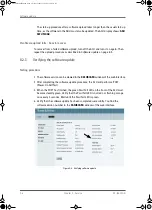
Page 131: ...nector of the ACU 3 Open your Internet browser and enter the IP address of the ACU The IP address is http 192 168 0 1 default For further details on network setup see Configuring the LAN network on page 6 24 4 The web interface opens directly with the DASHBOARD page 5 Click SERVICE from the left navigation pane The Upload page is displayed 6 Click Browse and locate the new software file 7 Click Up...

Page 132: ...sting procedure 1 The software version can be viewed in the DASHBOARD window of the web interface 2 After completing the software update procedure the ACU will perform a POST Power On Self Test 3 When the POST has finished the green Pass Fail LED on the front of the ACU must become steadily green Verify that the Pass Fail LED is not red nor flashing orange once every 2 seconds Wait until the Pass ...

Page 133: ... the web interface HELPDESK Self test For details on error messages after a POST or a self test see Event list on page 8 3 Means of signalling The SAILOR 100 Satellite TV provides various methods for signalling the system status LEDs on the front panel of the ACU are used to signal Power on off TV Ready Fail Pass The built in web interface of the ACU shows any events BITE error codes with a short ...

Page 134: ... Power Steady green Power supply OK Off No power Service Steady green Module ok application running Flashing green Waiting for upload Flashing red green Uploading application Steady red Module error or loading error Table 8 1 LEDs of the ADU modules Figure 8 5 LEDs on the ACU LED Behavior Description Power Steady green Power supply OK Steady red Power supply failure Off No power TV Ready Steady gr...

Page 135: ...r replacement Fail Pass LED Steady red A fault which prevents operation is present in the system ACU ADU Flashing green A Power On Self Test POST or Person Activated Self Test PAST in progress The current status is displayed Flashing red Active BITE failure or warning The event is shown in the ACU display Steady green No faults LED Behavior Description Table 8 2 LEDs on the ACU Continued SAILOR100...

Page 136: ...their position Some modules are equipped with LEDs for status information and troubleshooting For instructions on how to open and remove the service hatch see Opening and removing the service hatch on page 3 20 1 GPS module 2 Television Interface Module TIM 3 DC Motor Driver Module for cross elevation DDM 4 Cross elevation motor and encoder Figure 8 6 ADU modules and motor stop switch SAILOR100IM ...

Page 137: ...t visible on photo 9 Polarisation motor 10 Polarisation Motor Module PMM 11 Inertial Sensor Module ISM 12 Elevation locking pin to lock the antenna dish in a fixed position for safety during service not visible on photo 13 Pedestal Control Module PCM 14 Service switch In switch off position the DC Motor Driver modules DDM and the Polarisation Motor Module PMM are turned off for safe conditions dur...

Page 138: ...le on photo 17 Azimuth encoder not visible on photo 18 Rotary joint not visible on photo 19 Feed horn Before contacting your service partner check the LEDs on all modules See LEDs of the ADU modules on page 8 8 and LEDs in the ACU on page 8 8 Figure 8 7 Above Deck Unit modules continued SAILOR100IM book Page 12 Friday January 18 2013 10 28 AM ...

Page 139: ...or after exchange of modules ADU POST error hardware error ACU POST error hardware error For information on the function of the LEDs see Status signalling with LEDs and status messages on page 8 7 For a list of all the error messages and warnings see Event messages overview on page C 1 8 6 2 Event list for troubleshooting You can use the event list for troubleshooting It is described in detail at ...

Page 140: ...Troubleshooting 8 14 Chapter 8 Service 98 136280 B SAILOR100IM book Page 14 Friday January 18 2013 10 28 AM ...

Page 141: ...Appendices SAILOR100IM book Page 1 Friday January 18 2013 10 28 AM ...

Page 142: ...SAILOR100IM book Page 2 Friday January 18 2013 10 28 AM ...

Page 143: ...IEC 60950 1 CEI IEC 60945 CEI IEC 60950 22 ADU cable type ACU to ADU Single 50 Ohm coax cable for Rx ACU ADU modem and power ADU cable connector at the ADU Female N Connector 50 Ohm ADU cable connector at the ACU Female N Connector 50 Ohm System power supply range 20 32 VDC Start up voltage 22 VDC guaranteed Total system power consumption 260 W peak without SAILOR Transmodulator 367 W peak with SA...

Page 144: ...ar sky including radome LNB Whole band worldwide single cable Tracking Receiver Internal whole band DVB S2 type supporting QPSK 8PSK and RSSI Polarisation Linear and circular polarisation automatic switch Elevation Range 25 to 125 Azimuth Range Unlimited Rotary Joint Ship motion angular Roll 30 Pitch 15 Yaw 10 Ship turning rate and acceleration 15 s and 15 s2 ADU motion linear Linear accelerations...

Page 145: ...perational 80 kt Survival 110 kt Ice Survival 25 mm 1 inch Solar radiation 1120 W m2 to MIL STD 810F 505 4 Compass safe distance 1 m to IEC 945 Maintenance scheduled None Maintenance unscheduled All electronic electromechanical modules and belts can be replaced through the service hatch Built in tests Power On Self Test POST Person Activated Self Test PAST Continuous Monitoring CM with error log P...

Page 146: ... 55 C Storage 40 C to 85 C Humidity IEC 945 protected 95 non condensing IP class IP31 Compass safe distance 1 m to IEC 945 Interfaces 1 x N Connector for antenna RF Cable 50 Ohm w automatic cable loss compensation 4 x F Connectors 75 Ohm for TV output 4 x Ethernet 2 x DB9 reserved for future use 1 x NMEA 2000 CAN bus and NMEA 0183 RS 422 for Gyro GPS compass input 1 x DC power input 1 x Grounding ...

Page 147: ... drawings 98 136280 B Appendix A Technical specifications A 5 AAAA Technical specifications A 2 Outline drawings A 2 1 ADU Figure A 1 Outline drawing ADU SAILOR100IM book Page 5 Friday January 18 2013 10 28 AM ...

Page 148: ...Outline drawings A 6 Appendix A Technical specifications 98 136280 B A 2 2 ACU Figure A 2 Outline drawing ACU SAILOR100IM book Page 6 Friday January 18 2013 10 28 AM ...

Page 149: ...8 136280 B Appendix A Technical specifications A 7 AAAA Technical specifications A 2 3 N connector interface on the ADU Figure A 3 N Connector interface on the ADU SAILOR100IM book Page 7 Friday January 18 2013 10 28 AM ...

Page 150: ...Outline drawings A 8 Appendix A Technical specifications 98 136280 B SAILOR100IM book Page 8 Friday January 18 2013 10 28 AM ...

Page 151: ...ment B 1 2 Safety First of all grounding of the system is required for safety reasons In the event of a lightning strike at the ADU a proper grounding of the system will provide a low resistance path to divert the strike discharge to seawater B 1 3 ESD Protection The ESD protection circuits in the ACU rely on proper grounding of the system in order to work properly Otherwise sensitive circuits wit...

Page 152: ...e cases it may not be possible to access the hull and at the same time place the ACU in a suitable place A way to insure good grounding and at the same time make it possible to ground the coax cable is to extend the ship ground plane by means of copper foil The maximum length of the foil is determined by the width of the foil Copper foil 5 cm wide Max 50 cm Copper foil 10 cm wide Max 100 cm Copper...

Page 153: ...oid corrosion It is always recommended to establish the shortest possible grounding path e g on steel hulls the ADU should be grounded directly to the hull 2 However due to the fact that this is not possible on e g fibreglass hulls nor is it preferable on aluminium hulls a number of alternative grounding methods are suggested in the following paragraphs Figure B 2 Grounding the ADU Note For optimu...

Page 154: ...e ship via one or more of its mounting bolts Make sure to remove painting dirt grease etc at the mounting holes in order to make good electrical contact to the hull Use serrated washers when securing the mounting bolts and seal the joint with protective coating to avoid corrosion Terminal grounded at a dedicated RF ground alternative In this case the ADU is grounded with a separate ground cable Th...

Page 155: ... alternative QWHQQD JURXQGHG ZLWK VHSDUDWH FDEOH QWHQQD 0DVW HOHFWULFDOO ERQGHG WR WKH VWHHO KXOO DVH 3ODWH QWHQQD LVRODWHG IURP WKH WKH KXOO QWHQQD JURXQGHG ZLWK PRXQWLQJ EROWV QWHQQD 0DVW HOHFWULFDOO ERQGHG WR WKH VWHHO KXOO DVH 3ODWH HOHFWULFDOO ERQGHG WR WKH KXOO WKRXJK WKH PDVW 5HFRPPHQGHG OWHUQDWLYH SAILOR100IM book Page 5 Friday January 18 2013 10 28 AM ...

Page 156: ... The ACU provides galvanic isolation as required from its input power terminals to the chassis grounding stud This way the isolated grounding arrangement is maintained B 4 2 Grounding the ADU If the mounting base of the ADU is electrically connected to the hull or any other ground potential than the ACU the ADU must be isolated at its mounting bolts by means of shoulder bushings and washers see B ...

Page 157: ...ed coax cable hence connecting the ADU to the ACU Grounding kit A heavy gauge wire with tinned strands min 6 mm2 can be used for this purpose Figure B 4 Alternative grounding for aluminium hulls QWHQQD 7HUPLQDO HDY DXJH LUH 5 URXQG DSDFLWLYH 25 VHSHUDWH JURXQG SODWH 7HUPLQDO URXQGLQJ LW SAILOR100IM book Page 7 Friday January 18 2013 10 28 AM ...

Page 158: ...any other ground potential than the ACU e g Lightning Ground the ADU must be isolated at its mounting bolts by means of shoulder bushings and washers see section B 6 3 However a ground connection must be established via one of the mounting bolts using a separate ground cable The ground cable must be routed parallel and in close proximity to the shielded coax cable hence connecting the ADU to the A...

Page 159: ...pply to the separate ground cable mentioned in the previous paragraphs The ground cable is constructed using an appropriate cable with a cross section area of at least 6 mm2 AWG10 and terminated with insulated ring crimp terminals see illustration below The crimp terminals must be a marine approved type e g the DuraSeal series from Raychem Figure B 6 Separate ground cable QWHQQD 0 QVXODWHG 5LQJ 7H...

Page 160: ...o be isolated from the mounting base shoulder bushings and washers must be used see figure B 7 Isolation of the ADU from the mounting base on page B 10 At the other end connect the ground cable as described in Grounding the ACU on page B 2 B 6 3 Isolation of the ADU from the mounting base In cases where the ADU is to be isolated from the mounting base shoulder bushings and washers accessories must...

Page 161: ... on the ADU as illustrated below Remember to seal the joint with protective coating to avoid corrosion Figure B 8 ADU isolation and grounding cable Isolating shoulder bush Plain washer stainless steel Spring washer stainless steel Plain washer stainless steel Serrated washer stainless steel Ground cable Ground cable SAILOR100IM book Page 11 Friday January 18 2013 10 28 AM ...

Page 162: ...le for grounding B 12 Chapter B Grounding and RF protection 98 136280 B B 7 Jumper cable for grounding Figure B 9 Jumper cable for grounding specifications SAILOR100IM book Page 12 Friday January 18 2013 10 28 AM ...

Page 163: ...t If there are problems with interference from HF transmitters it is advisable to mount ferrite clamps on the coax cable in order to provide suppression of induced RF The ferrites will have no effect on the differential mode signals but increases the impedance in relation to common mode RFI B 8 1 Recommendations Use 1 5 pcs hinged clamp cores e g the RFC or SFC series from Kitagawa mounted on the ...

Page 164: ...RF interference B 14 Chapter B Grounding and RF protection 98 136280 B SAILOR100IM book Page 14 Friday January 18 2013 10 28 AM ...

Page 165: ...ss LED in the LED panel of the ACU is lit As long as an event is active it is shown in the ACU display the Control Panel and the web interface in HELPDESK Event list or click the event icon on the DASHBOARD State the Event ID when contacting your service partner The event description might contain a number of digits in brackets e g 00000005 This is supplemental information and used for service and...

Page 166: ...d loaded correctly 0A007 0 Antenna ERROR XIM FPGA load The VIM TIM FPGA cannot be initialised and loaded correctly 0A008 0 Antenna ERROR XIM production Production calibration data stored in the VIM TIM module is invalid 0A00A 0 Antenna ERROR GPS initialisation The GNSS device cannot be initialised Check cable and GNSS device 0A014 0 Antenna ERROR AMB device discovery Missing one or more of the fol...

Page 167: ...ound at expected locations Check belt zero reference module and end stops Info See 0A021 0 0A023 0 Antenna ERROR Ele axis calibration Elevation axis zero reference or end stops not found at expected locations Check belt zero reference module and end stops Info See 0A021 0 0A025 0 Antenna ERROR Antenna calibration One or more errors occurred during antenna start up Info 0x00000001 Timeout calibrati...

Page 168: ...robably fixed by a restart of the system 0A03C 0 Antenna ERROR Xel DDM shutdown As Azi DDM shutdown but detected by the cross elevation motor control 0A03D 0 Antenna ERROR Ele DDM shutdown As Azi DDM shutdown but detected by the elevation motor control 0A03E 0 Antenna ERROR PMM shutdown As Azi DDM shutdown but detected by the polarisation motor control 0A03F 0 Antenna WARNING AMB timing This indic...

Page 169: ...ng information is missing in the antenna 0A050 0 Antenna ERROR Azi DDM communication Communication error between PCM and azimuth DDM Check SUB D connectors and cables 0A051 0 Antenna ERROR Xel DDM communication Communication error between PCM and cross elevation DDM Check SUB D connectors and cables 0A052 0 Antenna ERROR Ele DDM communication Communication error between PCM and elevation DDM Check...

Page 170: ...ct Zero slack high Mechanical slack may be too high Friction average peak high Mechanical friction is higher than expected Friction asymmetry high Mechanical imbalance may be too high 0A05A 0 Antenna WARNING Xel cal limits Cross elevation axis calibration result check limits exceeded Pointing performance may be degraded Info See 0A059 0 0A05B 0 Antenna WARNING Ele cal limits Elevation axis calibra...

Page 171: ...equested supply voltage 08069 0 ADM WARNING Blocking Zone The antenna has entered a blocking zone 0806D 0 ADM ERROR ADU power The ADU supply voltage is outside the allowed limits This could happen if the PSM fails to provide the requested supply voltage or if the voltage difference across the hotswap is unacceptable high 08070 0 ADM ERROR Satellite profile There is an error in the active satellite...

Page 172: ...g any errors the ADM is probably defective 08101 0 ADM ERROR PSM high voltage 48 V The ADM measures a different ADU voltage than expected Check for short circuit of the antenna coax connector If the problem is not solved by a restart and the PSM is not reporting any errors the ADM is probably defective 08102 0 ADM ERROR PSM 5 V power Internal voltage supply error of the ADM 08103 0 ADM ERROR ADM h...

Page 173: ...DM display Display hardware error in the KDM 09010 0 KDM ERROR KDM link SW version Link to the KDM module could not be established Either the KDM board is malfunctioning or if the system software has just been updated the software is too old and is not compatible with the KDM hardware 0B000 0 PSM ERROR PSM production data Missing or invalid production data in the PSM It should be replaced 0B001 0 ...

Page 174: ...List of ACU events C 10 Appendix C System messages 98 136280 B SAILOR100IM book Page 10 Friday January 18 2013 10 28 AM ...

Page 175: ...tor Driver Module DNS Domain Name System A system translating server names URLs to server addresses DVB Digital Video Broadcasting a set of standards relating to digital television E ESD ElectroStatic Discharge F FPGA Field Programmable Gate Array G GNSS Global Navigation Satellite System e g GPS GPL General Public License GPS Global Positioning System A system of satellites computers and receiver...

Page 176: ... signal without amplifying the noise signals hence the low noise part of LNB and to convert the high frequencies of the signal into lower frequencies a process called down converting for conveyance to the indoor equipment demodulator for processing LO Local Oscillator N NMEA National Marine Electronics Association standard A combined electrical and data specification for communication between mari...

Page 177: ...frequencies used for communications signals radio television cell phone and satellite transmissions or radar signals RFI Radio Frequency Interference A non desired radio signal which creates noise or dropouts in the wireless system or noise in a sound system RHCP Right Hand Circular Polarised T TIM Television Interface Module V VH Vertical High VL Vertical Low X XIM Xim Interface Module term for t...

Page 178: ...Glossary Glossary 4 98 136280 B SAILOR100IM book Page 4 Friday January 18 2013 10 28 AM ...

Page 179: ... cable loop DC resistance 3 22 ADU events C 2 aluminum hulls grounding B 6 antenna drainage 3 15 grounding recommendations B 3 installation location 3 3 isolation from mounting base B 10 mast design 3 7 obstructions 3 4 opening 3 20 stabilization 2 3 antenna dish position fix 2 5 8 11 attenuation ADU cable 3 22 azimuth adjustment 6 20 6 21 azimuth calibration 6 4 B baud rate NMEA 0183 4 4 BITE tes...

Page 180: ...37 IP address 6 43 software version 6 43 corrosion smoke deposits 3 15 coverage 6 15 6 39 current start up peak 5 1 D DC connector 4 2 DC Input connector 4 2 DC output connector 4 3 default reset to factory settings 6 35 default gateway 6 26 degradation due to the radar 3 14 Ku band connection 3 13 DHCP client 6 25 DHCP server 6 25 diagnostic report 6 31 8 2 dim display 6 38 display ACU descriptio...

Page 181: ...s B 8 recommendations B 2 steel hulls B 4 terminal B 2 gusset plates 3 7 H hatch remove 3 20 humidity in antenna 3 15 I impedance cable 5 3 ship 5 2 total 5 2 import configuration 6 35 installation ACU rack versionl 3 22 Interfaces 4 1 5 1 interference 3 12 from radar 3 12 RF B 13 IP address Control panel 6 43 for web interface 6 2 8 5 static 6 25 L LAN cable type 4 5 connector 4 5 network setup 6...

Page 182: ...connector 4 4 LEN 4 4 NMEA 0183 baud rate 4 4 notifications 8 3 O obstructions distance and size 3 4 On Off switch rack version 4 2 opening antenna 3 20 options order number 2 11 order number options 2 11 order numbers 2 11 outline drawing ACU rack version A 6 ADU A 5 P password administrator 6 32 change 6 33 PAST 8 7 peak current 5 1 permissions user 6 34 Person Activated Self Test 8 7 placing th...

Page 183: ... 31 server setup SMTP 6 27 service hatch lock 3 20 remove 3 20 setup diagnostic report 6 31 e mail 6 27 for statistics report 6 27 statistics report 6 28 user permissions 6 34 shadowing 3 4 ship motion centre 3 6 site map 6 8 smoke deposits 3 15 SMTP server 6 27 SMTP login 6 27 software license ii software update 8 5 software version 1 1 ACU 6 43 control panel 6 43 verify 8 6 source impedance meas...

Page 184: ...racking type 6 15 DVB S 6 15 troubleshooting diagnostic report 8 2 TT number 2 11 TV satellite 6 16 U updating software 8 5 upload configuration 6 35 user permissions 6 34 setup 6 34 W warning messages C 1 warnings 8 3 web interface browser settings 6 10 connect 6 2 6 3 navigating 6 10 Wiring 4 1 5 1 X XIM 8 13 XIM data modify 6 34 Z Zeroconf 6 26 SAILOR100IM book Page 6 Friday January 18 2013 10 ...

Page 185: ......
Page 186: ...info thrane com thrane com 98 136280 B ...

Reviews: