Interfaces of the SAILOR 100 Satellite TV ACU
4-2
Chapter 4: Interfaces
98-136280-B
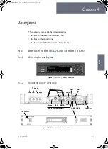
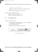
The connector LAN on the front panel is typically connected to the service port at LAN3
with a straight Ethernet cable. Then you can access the service port from the front of
the ACU rack version.
4.1.3
DC Input connector
Provide DC power to the ACU, for example by using the TT-6080A Power Supply or
24 VDC from the vessel’s power supply.
DC input:
Female plug (Weidmuller, Part number 1930050000) for wires up to
AWG10/6 mm
2
.
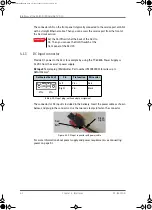
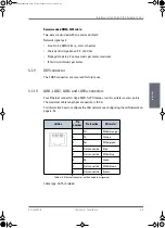
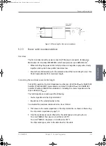
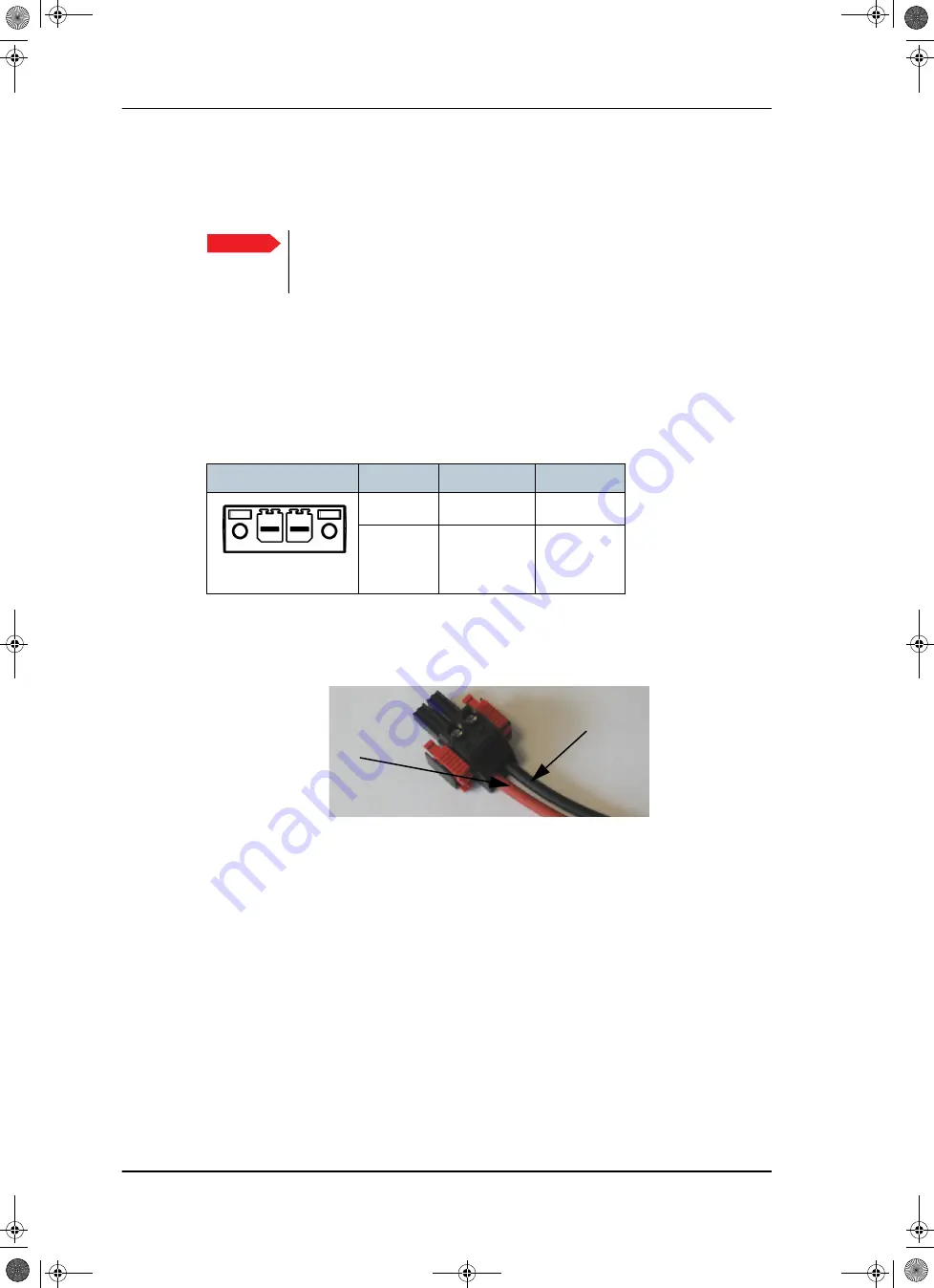
The connector for DC input is included in the delivery. Insert the power cable as shown
below, and plug in the connector. Use the two red clamps to fasten the connector.
For more information about power supply and power requirements see
Important
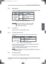
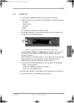
Set the On/Off switch at the back of the ACU to
On. Then you can use the On/Off switch at the
front panel of the ACU 19.
Outline (on the ACU)
Pin
Pin function
Wire color
Left
Vin+
Red
Right
Vin-
Black
Table 4-1: DC Input plug, outline and pin assignment
Figure 4-3: DC Input connector with power cable
Vin+
Vin-
Black
Red
(right)
(left)
SAILOR100IM.book Page 2 Friday, January 18, 2013 10:28 AM
Summary of Contents for 100
Page 1: ...INSTALLATION MANUAL SAILOR 100 Satellite TV ...
Page 2: ......
Page 8: ...vi 98 136280 B SAILOR100IM book Page vi Friday January 18 2013 10 28 AM ...
Page 141: ...Appendices SAILOR100IM book Page 1 Friday January 18 2013 10 28 AM ...
Page 142: ...SAILOR100IM book Page 2 Friday January 18 2013 10 28 AM ...
Page 178: ...Glossary Glossary 4 98 136280 B SAILOR100IM book Page 4 Friday January 18 2013 10 28 AM ...
Page 185: ......

