Chapter 4: Hardware interfaces
52
ISDN interface
4.6.2 Pin-out
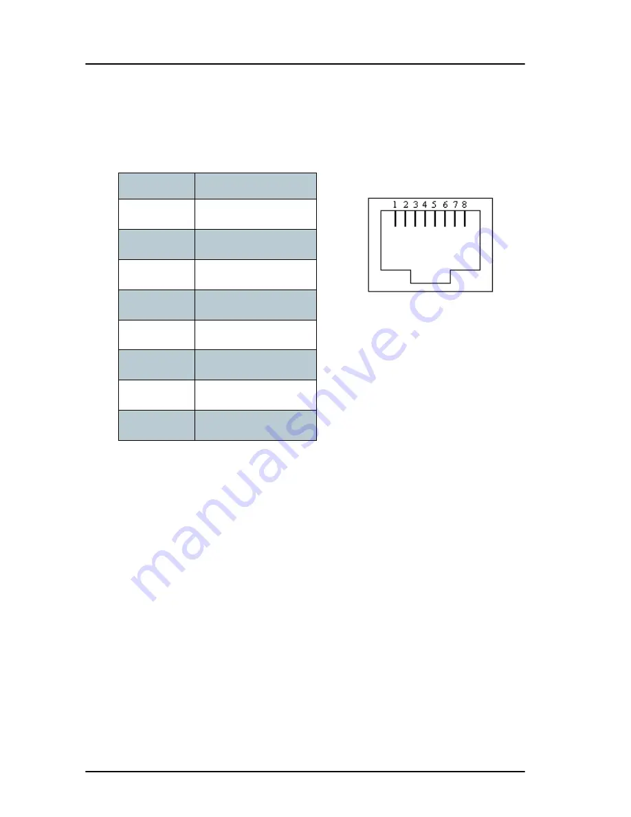
The figure and table below show the connector outline and pin assignments.
Pin number
Pin function
1
not connected
2
not connected
3
Rx+ (c) input
4
Tx+ (d) output
5
Tx- (e) output
6
Rx- (f) input
7
not connected
8
not connected
RJ-45 female connector
Summary of Contents for 500 FleetBroadband
Page 1: ......
Page 2: ...SAILOR 500 250 FleetBroadband INSTALLATION MANUAL ...
Page 16: ...Table of contents xiv ...
Page 22: ...Chapter 1 System units 6 IP handset and cradle ...
Page 60: ...Chapter 3 Connecting power 44 Remote on off ...
Page 100: ...Chapter 7 Troubleshooting 84 Logging of events ...
Page 124: ...Appendix B Technical specifications 108 SAILOR FleetBroadband terminal ...
Page 146: ...Appendix C Grounding and RF protection 130 Electrostatic Discharge ...
Page 154: ...Index 138 ...


