2 INSTALLATION
RT2048
4.
With AUX INTERFACE OPTION installed
Part no. 625473
(AUX1, AUX2 and MUTE functions) (Distress and Selcall functions are also mounted).
a.
AUX2, when information on certain channels is wanted, i.e. controlling a watch keeping
receiver, the AUX2 information can be used, a relay is controlled from the microprocessor.
Max. contact load: 100V AC/24V DC - 2A.
b.
AUX1, when function code in Prom 1 is enabled, AUX1 is free programmable on all
international channels (“0” or “1”).
Standard programming on international channels is “0”.
Max. contact load: 100V AC/24V DC-2A.
c.
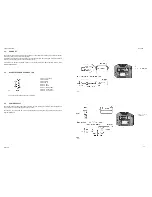
MUTE, makes it possible to mute AF power amplifier from external equipment.
Activated by a make function between pin 5 and pin 8 in P1 on option board.
5.
With BUS INTERRUPT OPTION installed
Part no. 626945
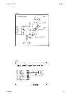
This module is used for interface to VHF DSC RM2042.
6.
With ATIS OPTION installed
Part no. 728665
The module 628652 is used for interface to ATIS module 626707, which is mounted on this PCB.
For circuit description and programming of ATIS option please refer to Appendix A - ATIS OPTION
25662A
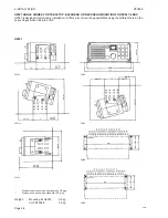
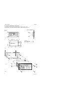
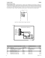
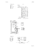
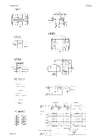
COMPONENT LOCATION FOR SPECIAL OPTIONS MODULES
VALID FOR 625661 / 625660 / 625473
Seen from component side
Seen from component side
with upper side tracks.
with lower side tracks.
PCB rev. 25473
0820
Page 2-8
Summary of Contents for RT2048 VHF
Page 1: ...INSTALLATION MANUAL SAILOR RT2048 VHF ...
Page 4: ......
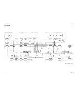
Page 11: ...1 INTRODUCTION RT2048 Page 1 7 9403 BLOCK DIAGRAM ...
Page 12: ......
Page 22: ...2 INSTALLATION RT2048 Page 2 10 9346 626945 625473 ...
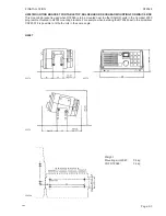
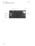
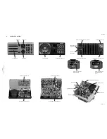
Page 24: ...2 INSTALLATION RT2048 2 8 REAR VIEW OF VHF RT2048 25567 9350 Page 2 11 ...
Page 26: ......
Page 31: ...3 Service RT2048 3 10 PIN CONFIGURATIONS Page 3 5 ...
Page 32: ...3 SERVICE RT2048 Page 3 6 ...
Page 33: ...3 Service RT2048 Page 3 7 ...
Page 34: ...3 SERVICE RT2048 Page 3 8 ...
Page 38: ...5 CIRCUIT DESCRIPTION AND SCHEMATIC DIAGRAMS RT2048 Page 5 2 ...
Page 89: ......
Page 90: ...Thrane Thrane A S info thrane com www thrane com M2048GB Issue E 0820 ...


