5.
CIRCUIT DESCRIPTION AND SCHEMATIC DIACRAMS
5.1.
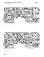
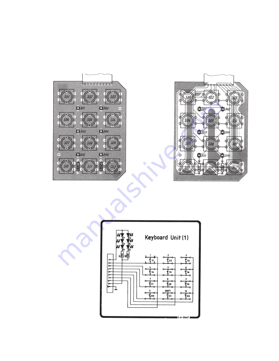
KEYBOARD UNIT (MODULE 1)
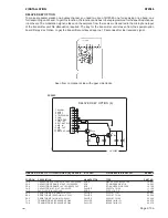
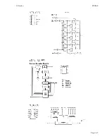
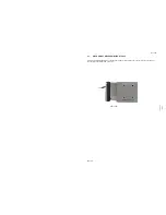
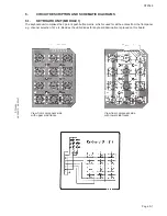
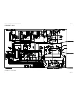
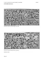
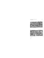
The keyboard unit comprises the 3 point 4 push button matrix, which is used for all the entries from the front panel
e.g. channel selection, 1W etc. Besides the LED-diodes for keyboard illumination is placed on this board.
View from component side
with upper side tracks.
View from component side
with lower side tracks.
Page 5-1
RT2048
RT2048A
4-6-25447D 4-0-25447
Summary of Contents for RT2048 VHF
Page 1: ...INSTALLATION MANUAL SAILOR RT2048 VHF ...
Page 4: ......
Page 11: ...1 INTRODUCTION RT2048 Page 1 7 9403 BLOCK DIAGRAM ...
Page 12: ......
Page 22: ...2 INSTALLATION RT2048 Page 2 10 9346 626945 625473 ...
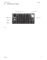
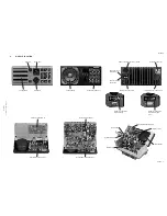
Page 24: ...2 INSTALLATION RT2048 2 8 REAR VIEW OF VHF RT2048 25567 9350 Page 2 11 ...
Page 26: ......
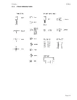
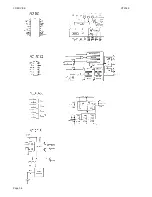
Page 31: ...3 Service RT2048 3 10 PIN CONFIGURATIONS Page 3 5 ...
Page 32: ...3 SERVICE RT2048 Page 3 6 ...
Page 33: ...3 Service RT2048 Page 3 7 ...
Page 34: ...3 SERVICE RT2048 Page 3 8 ...
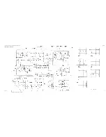
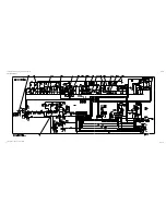
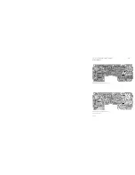
Page 38: ...5 CIRCUIT DESCRIPTION AND SCHEMATIC DIAGRAMS RT2048 Page 5 2 ...
Page 89: ......
Page 90: ...Thrane Thrane A S info thrane com www thrane com M2048GB Issue E 0820 ...

