52
Installation
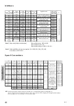
Interfaces
VHF Signal
Cable
Connection
Connection
Signal
description
Ships
cable
Options connector
designation
p/n 539603
box
box
8 twisted pairs
or
15-pin D-sub male
5m
In from VHF External conn.
overall screen
pin 1
VDR+
Brown
X1-1
X2-1
pair no. 1
pin 2
VDR-
Brown/Wht
X1-2
X2-2
pair no. 1
pin 3
AUX2
Orange
X1-3
X2-3
pair no. 2
pin 4
AUX2 NO
Orange/Wht
X1-4
X2-4
pair no. 2
pin 5
AUX 1
Blue
X1-5
X2-5
pair no. 3
pin 6
AUX 1 NO
Blue/Wht
X1-6
X2-6
pair no. 3
pin 7
int_S
Green
X1-7
X2-7
pair no. 4
pin 8
int_Speaker -
Green/Wht
X1-8
X2-8
pair no. 4
pin 9
DSC CALL
Red
X1-9
X2-9
pair no. 5
pin 10
DSC CALL NO
Red/Wht
X1-10
X2-10
pair no. 5
pin 11
GND
Blk+Blk/Wht
X1-11
X2-11
Equipment ground
pair no. 8
pin 12
NMEA +
Yel
X1-12
X2-12
pair no. 6
pin 13
NMEA -
Yel/Wht or Blk
X1-13
X2-13
pair no. 6
pin 14
DSC ALARM
Purple
X1-14
X2-14
pair no. 7
pin 15
DSC ALARM NO Purple/Wht
X1-15
X2-15
pair no. 7
Housing
Screen
Chassis
Chassis
Screen
Screens
Note 1:
Relay contact ratings (resistive load)
Max. switched power: 30W or 60VA
Max. switched current: 1.0A
Max. switched voltage: 150VDC or 125VAC
in accordance with IEC61162-1
C
or
res
pondi
ng
ly
g
rou
ped
indi
vi
dua
l c
abl
in
g
NMEA data input from external
position sensor (see note 2)
Relay contact closing on incoming
Distress alert (see note 1)
Relay contact closing on incoming
DSC call (see note 1)
Note 2:
Following NMEA sentences are supported: GLL, RMC, ZDA, GGA, VTG, GNS
Mixed Rx/Tx audio output for
recording. Galvanically isolated,
balanced signal, 0dBm into 600
Ω
VHF internal speaker output,
nom. 5W into 8
Ω
.
Relay contact closing on event pre-
defined through service
programming (see note 1)
Relay contact closing on event pre-
defined through service
programming (see note 1)
Sparc II Connections
VHF
Signal
Cable
Connection box Connection box Connection box Connection box Alarm panel
Signal description
Ships cable
SPARC connector
designation
p/n 56.114
In from VHF
Out to CU1 or Out to CU2 or to alarm panel
"VHF"
8 twisted pairs
15-pin D-sub female
5m
extension box
extension box
connector X3
overall screen
pin 1
12.5VDC+
Red/Wht
X3-1
X4-1
X5-1
X6-1
Power to CUs
pair no. 8
pin 2
DATA_+
Yel
X3-2
X4-2
X5-2
X6-2
3
pair no. 1
pin 3
DATA_-
Yel/Wht
X3-3
X4-3
X5-3
X6-3
5
pair no. 1
pin 4
TX_AF+
Blue/Wht
X3-4
X4-4
X5-4
X6-4
pair no. 2
pin 5
TX_AF-
Blue
X3-5
X4-5
X5-5
X6-5
pair no. 2
pin 6
GND
Red
X3-6
X4-6
X5-6
X6-6
2
Equipment ground
pair no. 6 & 8
pin 7
12.5VDC+
Orange/Wht
X3-7
X4-7
X5-7
X6-7
9
Power to CUs
pair no. 6
pin 8
RX_AF+
Green/Wht
X3-8
X4-8
X5-8
X6-8
pair no. 3
pin 9
RX_AF-
Green
X3-9
X4-9
X5-9
X6-9
pair no. 3
pin 10
12.5VDC+
Blk/Wht
X3-10
X4-10
X5-10
X6-10
Power to CUs
pair no. 7
pin 11
EXT.S
Brown
X3-11
X4-11
X5-11
X6-11
pair no. 4
pin 12
EXT.Speaker -
Brown/Wht
X3-12
X4-12
X5-12
X6-12
pair no. 4
pin 13
GND
Blk
X3-13
X4-13
X5-13
X6-13
Equipment ground
pair no. 7
pin 14
L
Purple
X3-14
X4-14
X5-14
X6-14
pair no. 5
pin 15
Lineout -
Purple/Wht
X3-15
X4-15
X5-15
X6-15
pair no. 5
Housing
Screen
Chassis
Chassis
Chassis
Chassis
Screen
EXT LS
X8-1
X9-1
EXT LS
X8-2
X9-2
NOTE:
In case of connecting CU1 and/or CU2 directly to Connection Box, i.e. not utilizing Extension Box for connecting each CU,
jumpers J1/J2 and/or J3/J4 in Connection Box must be removed in order to disconnect VHF Ext. Speaker (VHF LS) output from these terminals
and make available the CU Ext. Loudspeaker (CU LS) connections instead.
Rx-audio line output,
balanced signal, 0dBm
into 600
Ω
External speaker output,
nom. 5W into 8
Ω
(
see
NOTE
)
SPARC II-bus Data
SPARC II-bus Rx audio
SPARC II-bus Tx audio
VHF radio external
speaker output, nom. 5W
into 8
Ω
0611
Summary of Contents for RT5022 VHF DSC
Page 1: ...SAILOR RT5022 VHF DSC SAILOR RT5020 VHF DSC Duplex OPERATION MANUAL...
Page 2: ......
Page 66: ......
Page 67: ......
Page 68: ...Thrane Thrane A S info thrane com www thrane com B5022GB0 Issue L 09 02...

