VHF 5000 System
Functional unit description
1-5
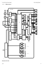
The baseband module is attached to all modules in the radio and is in control of these modules as well as
peripheral interfaces. The baseband module has two main functionalities that are handled separately by a
microprocessor and a digital signal processor.
The microprocessor controls the mode of the radio based on input from the user interface and incoming DSC
messages. This includes display and keyboard control, configuration of the RF board for receiving and
transmitting on a specified channel, and composition and decoding of DSC messages.
The digital signal processor performs all audio signal processing and audio switching on the received and
transmitted signals. The FM demodulated signals from the main receiver and the watch receiver is fed into the
DSP where the following functions are located: FSK demodulation, ATIS demodulation, squelch, replay
buffering, de-scrambling, volume control, and general filtering. After processing of the RX signal the processed
signal is routed to the 2-channel audio power amplifier and external connectors for handset and control units.
The digital signal processor is responsible for generating and handling the relevant modulation signal for the
RF board. The modulations signal can consist of Voice, ATIS message, DSC message, or Scrambler data.
During voice transmission the DSP carries out compression, pre-filtering and optional scrambling of voice
signals from the microphone. During transmission of DSC and ATIS messages the DSP carries out the FSK
modulation. The modulation indexes related to the different modulation signals are adjusted internally in the
DSP.
Front Control Unit
The MKD module is connected to the baseband board through 4 interfaces determined for sending keyboard
data, receiving display data, controlling keyboard light, and connecting speaker. The baseband module solely
carries out the control of these interfaces.
1.1.3
Switch mode power supply
Input
filter
Transformer
and
switch stage
Rectifier
and
choke
Output
filter
Error
amplifier and
opto-coupler
On/Off circuit
and switch
controller
+12.5V DC
GND
10-32V DC
from
battery
3.3V DC
converter
+3.3V DC
40365
on/off
The input power plug with filter and fuse is an integrated part of the power supply and must not be replaced by
unauthorised parts. The fuse is accessible from the outside below the power input cable. The module is reverse
polarity protected by a diode.
ON/OFF function
This power supply has a special function which means that if the battery connection to the radio accidentally
is interrupted for a few minutes, the radio will switch on again by it self when power is back. However, this function
is only valid if the radio has been switched on for a while and if the break is shorter than a few minutes.
Power converters
The main power converter is based on a push-pull principle and converts the battery voltage (10-32VDC) into
12.5VDC for the PA and internal supplies. A 3.3V DC converter works from the 12.5V to generate the 3.3V supply
for the Base Band module.
0608
Summary of Contents for RT5022
Page 2: ......
Page 4: ...VHF 5000 System 0930 ...
Page 16: ...Maintenance VHF 5000 System 2 2 ...
Page 70: ...Feature sales VHF 5000 System 4 2 ...
Page 82: ...Installation VHF 5000 System 5 12 0608 ...
Page 83: ...VHF 5000 System Installation 5 13 0608 ...
Page 84: ......


