VHF 5000 System
Functional unit workshop service
3-13
•
Fasten the E-profile to rear chassis by means of the
two (2) screws installed from the back of the radio.
Carefully observe that the E-profile does not rest
on top of any components of the PSU module.
1007
•
Install the Prespan carbon sheet between coil and
the E-profile to ensure insulation of the coil from
chassis.
•
Carefully install a retainer clip over each of the
regulator transistors to hold these tight against the
E-profile to ensure proper cooling.
•
Using a piece of cardboard of approx. 1mm
thickness, check and ensure sufficient spacing of
clips to surrounding components to avoid clips
shorting to such.
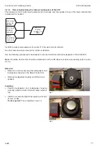
Fig. 16
Fig. 15
Fig. 14
Fig. 17
Summary of Contents for RT5022
Page 2: ......
Page 4: ...VHF 5000 System 0930 ...
Page 16: ...Maintenance VHF 5000 System 2 2 ...
Page 70: ...Feature sales VHF 5000 System 4 2 ...
Page 82: ...Installation VHF 5000 System 5 12 0608 ...
Page 83: ...VHF 5000 System Installation 5 13 0608 ...
Page 84: ......


