background image

13

Installation

IRIDIUM

0225

Precautions
In order to avoid interference or any other kind of disturbances from other systems on board, there are a few
precautions to take note of:

Radars
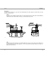
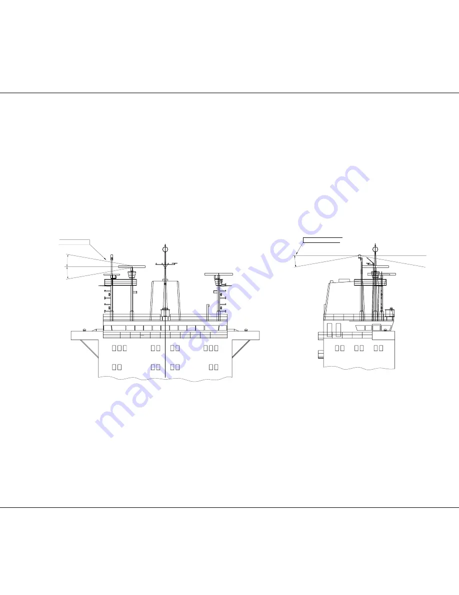
According to any installation guide for radars it is of vital importance that any other units are kept outside the
radiation beam of the radar. Please consult fig. 3, showing what area to avoid:

36622A

10°

e.g. from the radar

Avoid interference

10°

10°

Unobstructed view until
10° below the horizon

GPS
Tests have shown that only in case very old GPS equipment is used, a user may expect a minor influence on
the GPS originated from the Iridium equipment. This can be avoided by ensuring a distance of at least 1 m
between the two antennas.

Summary of Contents for SC4150

Page 1: ...SAILOR SC4150 Installation Manual Single channel Unit...

Page 2: ...climatic conditions to the biggest ships EuroCom Industries A S ECI develops and produces high technology maritime communications equipment under the brandname Sailor ECI is one of the world s largest...

Page 3: ...ion 5 2 2 Where to Place the Satellite Transceiver Box 7 2 3 How to Mount the Satellite Transceiver Box 8 2 4 How to Put on the Finishing Cover 9 2 5 How to Insert the SIM Card 10 2 6 How to Remove th...

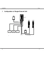
Page 4: ...0225 1 Configuration of Single Channel Unit L1 35423E 10 32V DC PABX Phone DTE 2 3 4 1 Antenna Unit Max cable loss 3dB Iridium L1 L2 100 metres L2 Box Connection 5 1 Handset Control Handset Transceiv...

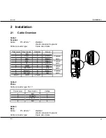
Page 5: ...te Twisted 3 data 3 brown pairs 4 AF 4 green Twisted 5 AF 5 yellow pairs 6 GND 6 grey Twisted 7 24V DC 7 pink pairs 8 RX_AF 8 blue Twisted 9 RX_AF 9 red pairs shield GND shield 2 3 4 5 6 7 8 9 1 10 36...

Page 6: ...erial GND 5 6 data set ready 6 7 request to send 7 8 clear to send 8 9 RI 9 shield GND shield Cable 4 Power supply Front view Pin no Description Colour 1 10 32V DC red 2 0V DC black 3 NC white 4 GND g...

Page 7: ...199 C61 R123 C113 C62 C172 C120 C57 N4 V66 V62 C28 N9 C36 C209 C210 V61 R35 R199 V68 R200 R214 R97 V60 R198 V57 C171 C99 C41 C109 R43 R83 N5 C68 N8 R6 C147 R38 N13 C86 C106 R39 R220 R119 R40 R151 C103...

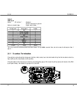
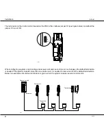
Page 8: ...a system only including a transceiver unit and one control unit no changes in the default termination is needed If the system includes more than one control unit it is needed to remove some of the def...

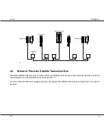
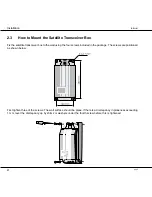
Page 9: ...Satellite Transceiver Box Mount the satellite transceiver box in a place where it is sheltered from the wind protected from the salty and humid sea atmosphere The temperature must not exceed 55 C To...

Page 10: ...wall using the four screws included in the package The screws are positioned as shown below First tighten three of the screws The wall surface should be plane If there is a discrepancy in planeness ex...

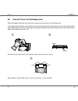
Page 11: ...be shut Press the hooks inside the finishing cover down on the two thin edges of the satellite transceiver box While pressing let the two plastic spears inside the finishing cover into the two square...

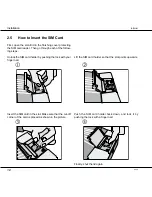
Page 12: ...w ing steps Unlock the SIM card holder by pushing the lock with your finger nail Lift the SIM card holder so that the slot points upwards 0225 Insert the SIM card in the slot Make sure that the cut of...

Page 13: ...he satellite transceiver box as follows Put a screwdriver into the slot in the printed circuit board beside the SIM card reader and press gently to unhook the plastic spear While pressing with the scr...

Page 14: ...mounted on either a rail or a pole The fitting in fig 2 can be used at the top of a tube Please note that it is necessary to mount the cable and seal this connection securely before the antenna and f...

Page 15: ...that any other units are kept outside the radiation beam of the radar Please consult fig 3 showing what area to avoid 36622A 10 e g from the radar Avoid interference 10 10 Unobstructed view until 10...

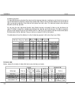
Page 16: ...se contact your dealer for further information The table below shows the distance to other Inmarsat equipment with and without use of filter 9505 ISU Protection Distance Main Lobe Metres Side Lobe Met...

Page 17: ...unit PSTN socket and the call can then be initiated from this telephone e g from the captain s cabin or the cargo control room The built in SMPS of 10 32 V DC generates the necessary current to suppor...

Page 18: ...16 Installation IRIDIUM 0225...

Page 19: ...ORU WHP WHPQXPEHU Power cable 56 140 TNC N adaptor 79 005 LBT 55 915 Controller PCB 638451 ID kit 49 310 Fuse 45 669 Scanbus male 9p Sub D 78 758 Scanbus female 9p Sub D 78 765 Housing 9p Sub D 78 745...

Page 20: ......
Reviews: