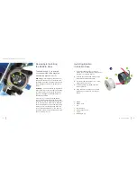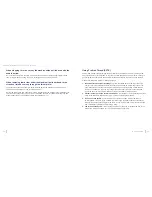
Clutch Will Not Disengage
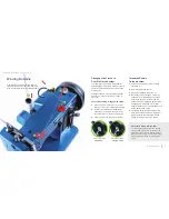
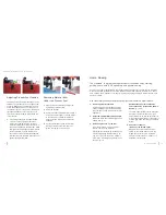
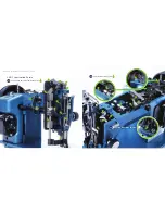
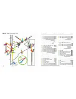
If the clutch will not disengage, first remove the reverse threaded Posi-Pin nut (p. 61,
2
) from the
balance wheel (
6
). Remove the balance wheel. Polish and lubricate the Posi-Pin bushing shaft (
4
).
Slide the balance wheel back on and screw the Posi-Pin nut (
2
) down.
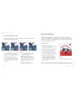
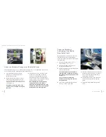
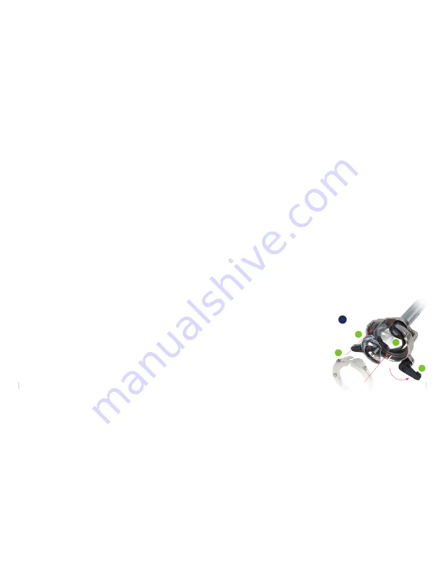
Removing the Hook to Clean the Shuttle Race
Guide Shaft and Free Thread Jams
Perform these steps with care:
1.
Move the needle to its highest point by
turning the balance wheel toward you.
2.
Remove the bobbin case/bobbin.
3.
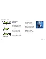
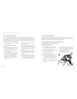
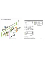
Turn each lever (
36
A
) one half turn away
from the retaining ring (
B
).
4.
Pull the axle of the hook to remove
retaining ring (
B
) and hook (
C
).
5.
Gently remove the accumulated lint and
thread from the retaining ring (
B
), hook
(
C
), and driver (
D
). Use a small brush to
clean the parts or blow out the debris.
6.
Replace hook (
C
) opposite driver (
D
). The
hook just rests in place. Be sure the axle
is facing out.
7.
Replace retaining ring (
B
) so that both
pins are under the black levers (
A
) when
turned. The polished side of the retaining
ring should be facing out.
8.
Replace the bobbin and bobbin case
before beginning to sew.
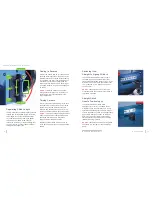
Inconsistent Stitch Tension
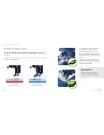
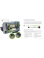
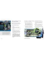
If you notice that you are getting inconsistent stitch tension or if your thread looks loose and
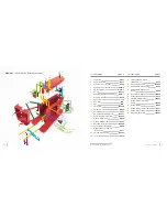
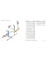
sloppy near the tension assembly under operation, check your take up spring (p. 28,
35
H
). If
the wire hook has broken off, you’ll need to replace the take-up spring. To do this, you’ll need to
disassemble the upper tension assembly. Keep track of how the parts are removed as they will
be replaced in the same manner (p. 28,
35
).
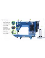
1.
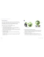
Pull the cover knob (
A
) straight off (wiggle
a bit if needed).
2.
Unscrew and remove the threaded
knob (
B
).
3.
Remove the big spring (
C
), the spring
holder (
D
), the two tension disks (
E
&
F
),
and the keyway washer with pip (
G
).
4.
Remove the old take-up spring (
H
) by
pulling it straight out.
5.
Slide the new take-up spring over the
core post (
I
) so that the pip on the back
faces in towards the machine and the
straight arm of the spring faces down
(approximately at a 6 o’clock position).
Push the spring in all the way.
6.
Spin the arm of the spring clockwise past
the slot in the core.
7.
While holding the spring arm in place,
slide the keyway washer (
G
) back onto the
core with the pip facing in, so the take-up
spring arm rests on the metal pip of the
washer.
8.
Replace the first tension disk (
F
) with the
convex side facing out. Add the second
tension disk (
E
) with the concave side
facing out.
9.
Replace the spring holder (
D
) with the
concave side facing out and the spring
(
C
). Screw the threaded knob (
B
) back on
the post and add the cover knob (
A
).
36
B
C
D
A
Ultrafeed
®
Guidebook: Troubleshooting the Ultrafeed®
30
29
www.sailrite.com

