


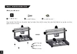


Part 2 - Mechanical Assembly
Step 1
:
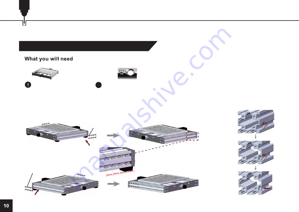
Align the X / Z-axis Gantry Fixing Nuts
Before we begin, place your 3020-PRO MAX CNC Base on a flat and level surface.
28
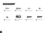
16 x Spring Loaded M5 T Nut
Base Assembly
Insert Spring loaded M5 T Nuts into the side of the profile. Do this by tilting the T Nut at
an angle as shown in the diagram below with the tapered side into the slot, be sure the
T Nuts are fully seated into the slot by pressing the T Nut flat. Then align the T Nuts to
match on both sides of the Y-axis according to the Gantry holes (See Diagram).
Spring Loaded
M5 T Nut
Spring Loaded
M5 T Nut
Step diagram for putting
the nuts into the profile:


