background image

VERS. 2017.06.12 

CM 401_MAN_EN 

BASIC SAFETY INSTRUCTIONS 

 
The CM 401 is exclusively designed for the cutting of construction products mainly on construction 
sites. 
Uses other than the manufacturer's instructions shall be considered as contravening the regulations. 
The manufacturer  shall  not  be  held  responsible  for  any  resulting  damage.  Any  risk  shall  be  borne 
entirely  by  the  user.  Observing  the  operating  instructions  and  compliance  with  inspection  and 
servicing  requirements  shall  also  be  considered  as  included  under  use  in  accordance  with  the 
regulations. 

1.1  Symbols 

 
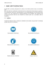
Important warnings and pieces of advice are indicated on the machine using symbols. The following 
symbols are used on the machine:  


Read operator's instructions 


Ear protection must be worn 


Hand protection must be worn 


Eye protection shall be worn 


Rotation direction of the blade 


Danger: risk of cut 


Summary of Contents for Norton Clipper CM 401 Series

Page 1: ...CM 401 OPERATING INSTRUCTIONS Translation of the original instructions...

Page 2: ...VERS 2017 06 12 CM 401_MAN_EN 2...

Page 3: ...83 CM 401 600 30 1 230V 70184626994 CM 401 600 40 3 400V 70184627004 CM 401 500 30 1 115V 70184627497 CM 401 600 30 1 115V 70184627498 is in conformity with the following Directives MACHINES 2006 42 C...

Page 4: ...cal documents Saint Gobain Abrasives 190 Bd J F Kennedy 4930 BASCHARAGE LUXEMBOURG This declaration of conformity loses its validity when the product is converted or modified without agreement Baschar...

Page 5: ...mission 12 2 6 Statement regarding noise emission 13 3 ASSEMBLY AND COMMISSIONING 14 3 1 Tool assembly 15 3 2 Electrical connections 15 3 3 Starting the machine 15 3 4 Water cooling system 16 4 TRANSP...

Page 6: ...age Any risk shall be borne entirely by the user Observing the operating instructions and compliance with inspection and servicing requirements shall also be considered as included under use in accord...

Page 7: ...rect mounting of the blade regularly Immediately remove damaged or badly worn blades as they endanger the operator whilst rotating Only fit NORTON diamond blades to the machine The use of other tools...

Page 8: ...the event of the machine breaking down or stopping for no apparent reason switch off the main electricity supply Only a qualified electrician is allowed to investigate the trouble and remedy the faul...

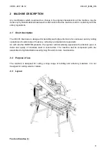
Page 9: ...ormance for onsite wet and dry cutting operations of a wide range of masonry refractory and natural stone products As with all other NORTON products the operator will immediately appreciate the attent...

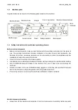
Page 10: ...to shaft for inspection and blade replacement when motor is switched off while fully protecting the blade when in operation Down feed and cutting depth adjustment 5 The spring loaded cutting head acti...

Page 11: ...ing can occur for two reasons a tripping under light load If connection is incorrect b tripping under heavy load If motor has been overloaded Anti tipping device 9 Two sheaves located on each side of...

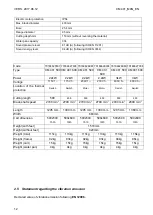
Page 12: ...5V 1 230V 1 230V 1 400V 3 400V 3 Location of the thermal protection Switch Switch Motor Motor Switch Switch Cutting length 500 600 500 600 500 600 Blade shaft speed 2700 min 1 2700 min 1 2700 min 1 27...

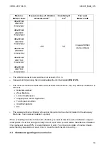
Page 13: ...ew machines Actual values may vary with site conditions in terms of Materials worked Wear Machine Lack of maintenance Inappropriate tool for application Tool in poor condition Unskilled operator Etc T...

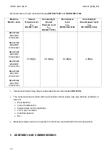
Page 14: ...983 CM 401 600 30 1 230V 70184626994 CM 401 600 40 3 400V 70184627004 CM 401 500 30 1 115V 70184627497 CM 401 600 30 1 115V 70184627498 81 dB A 2 5 dB A 94 dB A 4 dB A Values determined using the proc...

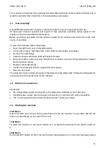
Page 15: ...t direction of rotation is correct Wrong direction of rotation blunts the blade quickly Replace outer blade flange Tighten the screw with spanner supplied for this purpose Shut the vent cover The blad...

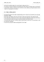
Page 16: ...water pan with clean water to approximately 2cm from top ensure that bottom of pump is fully immersed in water Open water tap at blade guard note that handle on water tap should be in line with water...

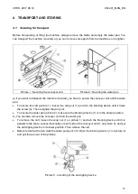
Page 17: ...the wing nut 1 and turn the blocking device until it takes the screw 3 Then retighten the wing nut To secure the water pan picture 2 make sure the blocking device 1 is in the shown position b You can...

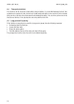
Page 18: ...e foot of the machine will automatically fold away You can then put the rear of the machine on the floor Then proceed the same way with the front foot 4 3 Long period of inactivity If the machine is n...

Page 19: ...M 401 5 2 Cutting methods To use the machine correctly you must face it with one hand on the handle of the cutting head and the other on the conveyor cart Always keep your hands away from the moving b...

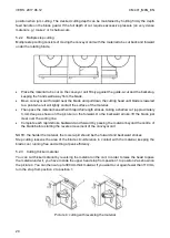
Page 20: ...rokes taking a shallow cut approximately 3 mm deep as shown on the picture on the forward On the backward stroke lift the blade just clear over the cutting line Complete each rapid stroke backward and...

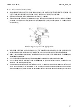
Page 21: ...as recommended by the manufacturer depending on the material to be worked the working procedure dry or wet cut to be carried out and the required efficiency Apply cooling water continuously whilst cut...

Page 22: ...ean Motor housing Clean Reachable nuts and screws Tighten up Maintenance of the motor Always perform the maintenance of the motor with the machine isolated from the electrical supply Cleaning of the m...

Page 23: ...he belts To adjust the belts firstly remove the belt guard by unscrewing the 4 nuts Loose the 4 motor bolts and shift the motor by using the two screws on the side To replace the belts move the motor...

Page 24: ...Defective switch CAUTION can only be solved by qualified electrician Defective motor Change motor or contact motor manufacturer Blade is not turning Belts not tightened or defective Check the belts te...

Page 25: ...VERS 2017 06 12 CM 401_MAN_EN 25 7 3 Circuit diagram 230V Motor...

Page 26: ...VERS 2017 06 12 CM 401_MAN_EN 26 115V Motor...

Page 27: ...VERS 2017 06 12 CM 401_MAN_EN 27 400V Motor CM 401 3kW 4 1 A...

Page 28: ...which is not always the quickest way Clear instructions will avoid problems and faulty deliveries If not sure please send us the defective part In the case of a warranty claim the part must always be...

Page 29: ...VERS 2017 06 12 CM 401_MAN_EN 29 Guarantee can be claimed and technical support obtained from your local distributor where machines spare parts and consumables can be ordered as well...

Page 30: ...VERS 2017 06 12 CM 401_MAN_EN 30...

Reviews: