background image


20 

Cleaning of the cooling air system 

Before cleaning, the engine must be stopped and allowed to cool down. 

  Remove parts of air duct. 

  Clean  all  air  guide  elements  and  the  complete  cooling  air  zones  on  the  cylinder  head, 

cylinder and flywheel blades without making them wet. Blow them with compressed air. 

  In case of moist or oily contamination, clean the complete area with a solvent, cold cleaner 

etc. according to its manufacturer’s instructions, then spray down with a powerful water jet.  
Do  not  point  the  spray  directly  at  electrical  equipment  or  connections,  or  dry  these 
immediately afterwards with compressed air. 

  Trace  the  cause  of  any  contamination  with  oil  and  have  the  leak  eliminated  by  a  HATZ 

service station.  

  Install the air guide elements previously removed. The engine must never be run without the 

air guide elements in position. 

  Immediately after re-assembly, run the engine until warm to prevent residual moisture from 

causing rust. 


Cleaning the filter cartridge  

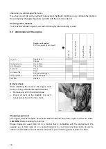
  Slacken off wing bolt (1 on left picture) and remove it with cover (2 on left picture). 

  Carefully pull out filter cartridge (1 on right picture) 


Clean all parts except the filter cartridge. Do not spray into the engine’s air intake when 
cleaning. 

  Blow through the filter cartridge from the inside, moving the jet of dry compressed air up 

and down until no further dust is expelled. Air pressure must not exceed 5 bar. 

  Tilt  the  cartridge  and  hold  it  against  the  light  (or  shine  a  light  through  it)  to  trace  any 

cracks or other damage. 

If there is even the slightest damage to paper filter element „2“ or sealing lips „3“, 
the filter element must not be reused.  

  By wet or oily contamination, change the cartridge. 


Checking of the valve clearance and of the fuel filter  

Contact a HATZ-Service station to make this maintenance. 

Summary of Contents for NORTON clipper CSB1 D13 H W Series

Page 1: ...CSB1 D13 HxW OPERATING INSTRUCTIONS...

Page 2: ...2...

Page 3: ...this product Floor saw Code CSB1 D13 HIW 70184613923 CSB1 D13 HMW 70184613924 is in conformity with the following Directives European Machinery Directive 2006 42 EC Electromagnetic Compatibility Dire...

Page 4: ...4...

Page 5: ...sioning 12 3 1 Tool assembly 12 3 2 Water cooling system 12 3 3 Starting the machine 13 4 Transport and Storing 15 4 1 Securing for transport 15 4 2 Transport procedure 15 4 3 Long period of inactivit...

Page 6: ...ance with inspection and servicing requirements shall also be considered as included under use in accordance with the regulations 1 1 Symbols Important warnings and pieces of advice are indicated on t...

Page 7: ...ttention is drawn to the use of BS2092 safety goggles in conformity with specified Processes No 8 of the Protection of Eyes Regulation 1974 Regulation 2 2 Part 1 For security reasons never leave the m...

Page 8: ...CSB1 D13 you have chosen is used for repair works in concrete and asphalt on highways and runways for trench sawing or cable loop cutting applications It can be used for either wet or dry cutting ope...

Page 9: ...one end The shaft is reduced to 25 4mm at the other end allowing an inner flange complete with dowel pinholes to be fixed The steel belt guard 6 is bolted to the mainframe of the machine It is coverin...

Page 10: ...ide sleeve for starting handle 8 Cylinder head cover 9 Cold start oil metering 10 Suspension lug 11 Tank filler cap 12 Oil drain plug governor housing 13 Oil drain plug governor side 14 Speed control...

Page 11: ...option Hydraulic oil with a viscosity equivalent to the one of an automotive oil SAE 20W 20 Starter Handle with kick back damping Blade raise system Manual Machine with code 70184613924 Hydraulic Mach...

Page 12: ...crew holding the removable outer flange with the 19mm wrench Remove the outer flange Clean the flanges and blade shaft and inspect for wear Mount the blade on the shaft ensuring that direction of rota...

Page 13: ...until stop 1 is reached In this position you can hear the automatic decompression system engage After the automatic decompression device has engaged at its limit stop turn the crank five times to bui...

Page 14: ...ing the engine because the crank handle was not turned firmly enough the brief reverse rotation at the handle tube separates the link between crank lug 2 and driving dog 3 If the engine begins to run...

Page 15: ...ng its wheels Rotate the handwheel on the side of the machine clockwise to move the machine forward and anticlockwise to move the machine backward Use the metal lifting eye located above the engine wh...

Page 16: ...rer depending on the material to be worked the working procedure dry or wet cut to be carried out and the efficiency required Make sure that the flanges securely hold the diamond blade Make sure that...

Page 17: ...wrench You can know re tension using a 36mm wrench to turn the tensioning device Retighten the maintaining screw and re assemble the belt guard To replace the belts loose the screw maintaining the te...

Page 18: ...Water trap Check Air cleaner filter Clean Change the cartridge Valve clearance Check and adjust Fuel filter Replace Oil level check When checking the oil level the engine must not be running and shoul...

Page 19: ...up to the MAX mark on the dipstick Run the engine for a short period then check the oil level again and top up if necessary Check that there is no leakage past screw plug on the oil filter Checking th...

Page 20: ...e run without the air guide elements in position Immediately after re assembly run the engine until warm to prevent residual moisture from causing rust Cleaning the filter cartridge Slacken off wing b...

Page 21: ...level Cylinder head temperature too high Check cooling air passage Stronger fault Contact nearest engine maintenance centre Engine lacks power Tank run dry Add fuel Air filter restricted Clean or repl...

Page 22: ...which is not always the quickest way Clear instructions will avoid problems and faulty deliveries If not sure please send us the defective part In the case of a warranty is claim the part must always...

Page 23: ...T Budafoki u 111 H 1117 BUDAPEST Tel 36 1 371 2250 Fax 36 1 371 2255 e mail nortonbp axelero hu United Kingdom Saint Gobain Abrasives Ltd Unit 2 meridian West Meridian Business Park Leicester LE19 1WX...

Page 24: ...24 www construction norton eu Saint Gobain Abrasives 190 Bd J F Kennedy L 4930 BASCHARAGE LUXEMBOURG Tel 352 50401 1 Fax 352 501633 e mail sales nlx saint gobain com...

Reviews: