background image

20

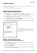
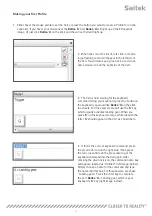
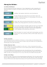
Altering Axis Attributes

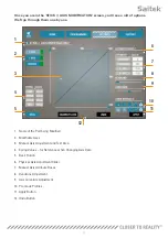
Axis Status Notifications

You’ll need to be aware of several notifications in the axis highlighter box when manipulating and 
applying axis data. On the left is a list of the current device’s axes. The colors indicate the status of 
each axis.

 
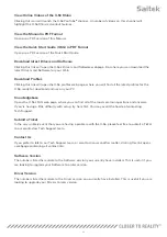
Light Blue in the larger box indicates the currently selected axis.

 
Orange in the larger box indicates the axis isn’t selected. Green in the 
smaller box indicates that the data on the settings page and the data on the 
device are in sync for this axis.

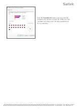
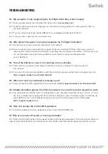
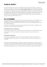
Yellow in the smaller box indicates that the data for this axis has been 
modified on the settings page but has not yet been synced to the device.

To sync data, click ‘Apply’ in the bottom right. The entire box will turn Yellow 
then start to fill up Green to indicate that the data on the settings page is 
being synced to the device. Once data is fully synced, the larger box will 
revert to Light Blue and the smaller box will stay Green.

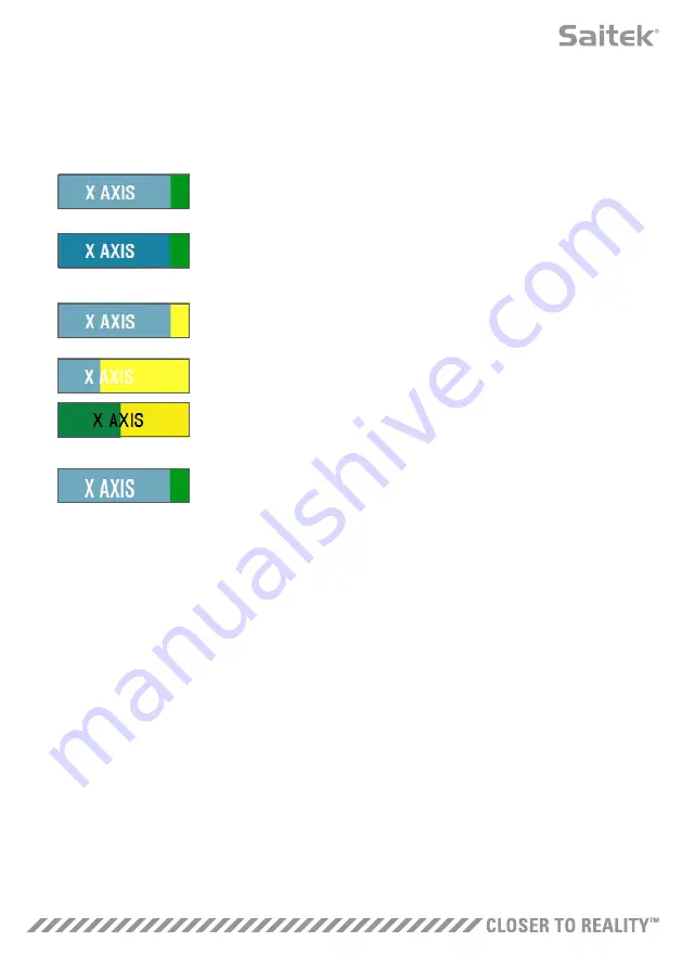
When the Axis box turns Green, the data from the settings page saves to the 
physical device. The main Axis box will then turn Blue and the slash will turn 
to Green.

Setting a Deadzone

To set a deadzone on an axis, whether it’s an S-Curve or a J-Curve, simply move the deadzone slider 
(part 8). You will see the axis start to split from the middle in the manual adjust area. The deadzone will 
become larger as the slider moves farther.

Setting a Response Curve

To set a response curve on an axis, whether it’s an S-Curve or a J-Curve, simply move the curvature 
slider. On an S-Curve setting you will see the curve turn snake-like, which indicates curvature above and 
below the center point the axis.

On a J-Curve setting you will see the whole axis curve as the slider moves. You can also change the 
curvature of either curve by moving the points in the manual adjustment area (part 4). If you move the 
points in the area, 2 for an S-Curve and 1 for a J-Curve, then the curve will adjust to the new points.

Setting an Axis Range

To set an axis range, simply move the Axis Range Adjustment Slider (part 5). This will shrink the data for 
that axis from the full negative side and from the full positive side. Now when you use the axis that you 
have just altered, the axis data output will only output up to the points that you have set in the settings. 

Summary of Contents for X-56 RHINO H.O.T.A.S. SYSTEM

Page 1: ...USER MANUAL COMBAT SERIES X 56 RHINO H O T A S SYSTEM HANDS ON THROTTLE AND STICK...

Page 2: ...ledge skill and endeavor went into the development phase Thanks to our dedicated pool of beta testers comprised of actual pilots and sim pilots we created a piece of hardware to satisfy your needs for...

Page 3: ...ith Trigger and 2 x Head Buttons E X Y and Rz Axes Elevator Aileron and Rudder Axes F Pinkie and Flying Pinkie G F E E L Spring System Pinkie Interaction menu Flying pinkie General Controls Stop Engin...

Page 4: ...Roll Analog Roll left right if no rudder pedals Left switch pinky frontside Left Digital Strafe left Roll Map zoom in out Throttle Analog With large deadzone if not using digital Left switch pinky fr...

Page 5: ...now installed B H U D Software 1 Download and install the X 56 Rhino Software from www saitek com 2 After clicking Run setup exe your Windows 8 system will drop out of the Metro Start screen and ask...

Page 6: ...ontinue 7 From the end screen click Finish Your drivers are now installed B H U D Software 1 Download and install the X 56 Rhino Software from www saitek com 2 After reading the Disclaimer select the...

Page 7: ...vice list and right click on this icon From the dropdown menu select Game Controller Settings 4 From the Game Controllers window you should see the X 56 Rhino listed and selected Click Properties and...

Page 8: ...7 From the Controller Test screen you can test all the functions axes buttons rotaries etc When you have completed your tests click OK twice to get back to the main desktop...

Page 9: ...n D 3 1 70 1 70 1 70 1 70 N mm Load Breakout BL FL WL x k 36 12 27 60 19 08 8 86 N Load P1L SoL FL SL x k 44 64 36 12 27 60 17 38 N Stress 8 x P x D 3 14 x d 3 608 50 492 38 376 25 236 90 N mm2 UTS M4...

Page 10: ...hen lift up The Seal Ring is stiff by design 3 Pry apart the Locking Clamps part D These pull apart from the stick but are under load from the spring Take one half off first hold the spring and then r...

Page 11: ...anual There are two ways to launch the H U D Software 1 From the desktop icon that looks like this 2 From the start menu bar Once the H U D Software launches you will be presented with the Home Screen...

Page 12: ...ct Related products that we feel that you would be interested in Live Facebook feed from Saitek Pro Flight Social media and website short cuts Saitek com Twitter YouTube Instagram etc Language selecti...

Page 13: ...indow In the PROGRAMMING Tab you can mimic your controller to directly copy any of the keyboard commands used in your favorite games The commands are then saved in what we call a Profile What is a Pro...

Page 14: ...yboard press the button on the keyboard you would like Button A on the stick to activate For this example we will use the G key which usually activates landing gear When you press G on the keyboard a...

Page 15: ...work in your game you must first save it as a Profile and then activate it This can be done with one click In the icon row just above the 3D image you will see an icon that looks like a blue target I...

Page 16: ...ge the view in the Profile Editor to be just programming Cells i e no image Clicking the Views button again will restore the default view and the image will reappear 5 Profile If you are working on a...

Page 17: ...ne or neutral zone is a part of the range in which an axis moves undetected by the drivers and without effect on in game progress It may be around the center point of the axis range or at either end o...

Page 18: ...10 11 3 1 Name of the Part being Modified 2 Modifiable Axes 3 Manual Axis Adjustment and Test Area 4 Spring Values for Reference when Changing Axis Data 5 Back Button 6 Physical Axis Adjustment Slide...

Page 19: ...ponse curve on the selected axis There is also a cross hair which will show the physical position of the axis you are manipulating 4 Spring Values This is a reference section when you are adjusting th...

Page 20: ...ade Profiles We have included a set a predefined curves to select This is to make it easier for those who do not wish to make their own curves There are two different types of curves to choose from 1...

Page 21: ...ice The main Axis box will then turn Blue and the slash will turn to Green Setting a Deadzone To set a deadzone on an axis whether it s an S Curve or a J Curve simply move the deadzone slider part 8 Y...

Page 22: ...tom right hand corner of the screen part 13 Once you ve hit Apply the axis icon part 1 will turn Yellow and progressively turn Green A Green end segment and Blue main axis indicates saved data For mor...

Page 23: ...Knowledgebase Opens the X 56 s FAQ web page where you can find all of the most common questions and answers If you re having a little difficulty with setup try here first You may avoid the hassle of...

Page 24: ...rollers panel as mentioned in the early part of this manual A 2 If you are still experiencing problems with the controller please contact the tech support team at http support madcatz com Tickets Subm...

Page 25: ...ay not cause harmful interference and 2 this device must accept any interference received including interference that may cause undesired operation Any changes or modifications not expressly approved...

Page 26: ...25...

Reviews: