HS2/AS2 Series
45
46
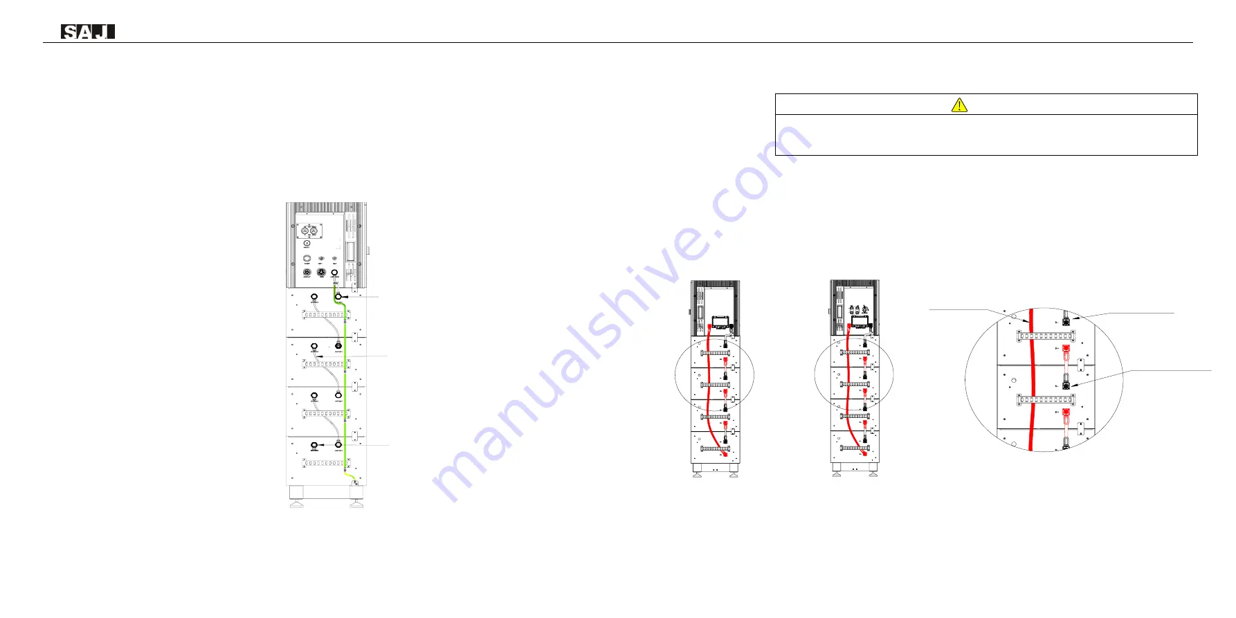
5.5 Connecting Battery COMM Cable
Step1: Connect link port 0 of inverter to link port 1 of battery 4 (the battery number can be varied, it should be
depended on the number of battery modules in the system)
Step 2: Repeat step 1 to connect the rest of the battery modules
Step 3: Insert a RJ45 plug to link port 0 of battery 1
Note: If the RJ45 plug is not installed, a communication error will occur.
Figure 5.14
Connecting battery COMM cable
5.6 Connecting Battery Power Cable
·
Power off the battery system before connecting the power cable to avoid high voltage danger
·
The electrical connection of high voltage battery systems must be operated by qualified technicians in accordance with
local and national power grid standards and regulations.
Step 1: Connect the power cable from B- port of inverter to B- port of the battery 4 (the battery number can
be varied, it should be depended on the number of battery modules in the system).
Step 2: Connect power cable from B+ port of battery 4 to B- port of battery 3.
Step 3: Repeat step 2 to connect the rest of the battery modules.
Step 4: Connect the B+ of inverter to B+ of battery 1.
Note: Please follow the following diagrams to connect cables.
Figure 5.15 Connecting battery power cables
Battery
1
Battery
2
Battery
3
Battery
4
HS2-5-10K-T2
Power cables
Power cables
Power cables
Battery
1
Battery
2
Battery
3
Battery
4
AS2-5-10K-T
RJ45 Plug
COMM
COMM
Battery 4
Battery 3
Battery 2
Battery 1


