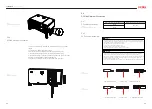
Note: The additional cable and OT/DT terminal should be prepared by user
themselves.
Remove the screw of grounding terminal and secure the additional
grounding cable by insert a screw into the screw hole in the OT/DT
terminal.
Note: Do not connect Aluminum OT/OD terminal with AC output terminal,
as it will have electrochemical reaction with AC output terminal and affect
the reliability of connection. Please choose the OT/OD terminal material
according to the cable conductor material as below.
USER MANUAL
SAJ SOLAR INVERTER
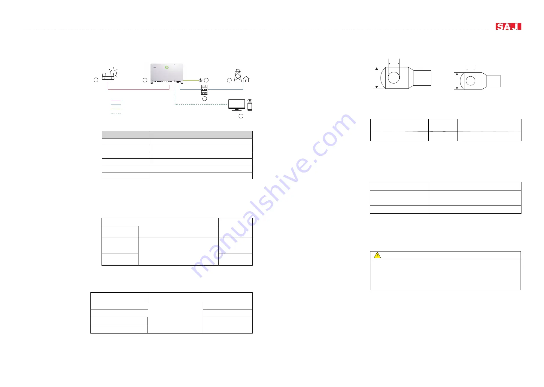
5.3
AC Connection
5.3.1
Electrical Connection
Overview
5.3.2
Cable Specification
5.3.3
Circuit Breaker
Specification
5.3.5
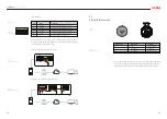
Connection of Additional
Grounding
Table 5.3
Recommended power grid connecting
cable specification
Table 5.5
Specification of cables
Table 5.6
Specification of cable conductor material
Table 5.4
Recommended circuit breaker specification
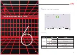
Fig 5.2
Electrical connection overview
Table 5.2
Electrical connection overview
27
28
1
2
3
4
5
DC
AC
GND
COMM
6
Item
Name
1
PV Array
C6 Inverter
Inverter enclosure grounding connection
Circuit Breaker
Grid
Monitoring Platform
2
3
4
5
6
Cable type
Scope (S)
Recommended
grounding cable (Spe)
External diameter
(mm)
Three core, four core
five core cable
Four single core cable
Spe≥S/2
14-32
38-66
95-240
Model
Recommended circuit breaker
rated voltage
Recommended circuit
breakerrated current
C6-100K-T9/C6-60K-T9-LV
C6-75K-T6/C6-50K-T6-LV
C6-110K-T12/C6-70K-T12-LV
C6-125K-T12
≥400V
160A
200A
225A
250A
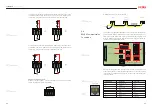
L1/L2/L3/N cable terminal PE cable terminal
Specification:
5.3.4
OT/OD Terminal
Specification
b
a
d
c
Fig 5.3
OT/OD terminal
Cross-sectional area of cables(mm²)
L1/L2/L3/N cable terminal M12 size a≤46mm, 13mm≤b≤15.5mm
PE cable terminal
M8 size c≤30mm, 8mm≤d≤11mm
Cable conductor material
Recommended OT/OD terminal material
Copper
Copper
Copper clad aluminum
Copper
Aluminum
Copper to aluminum adapter terminal
WARNING
· The ground connection of this additional grounding connection cannot replace the AC
cable PE terminal connection.
· Make sure that all the grounding points on the enclosures are equipotential connected
when there are multiple inverters
· Connect this additional grounding cable before AC cable connection, DC cable connec
-
tion and communication cable connection.


