5-003
RAMMING SYSTEM
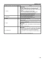
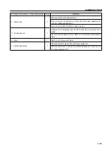
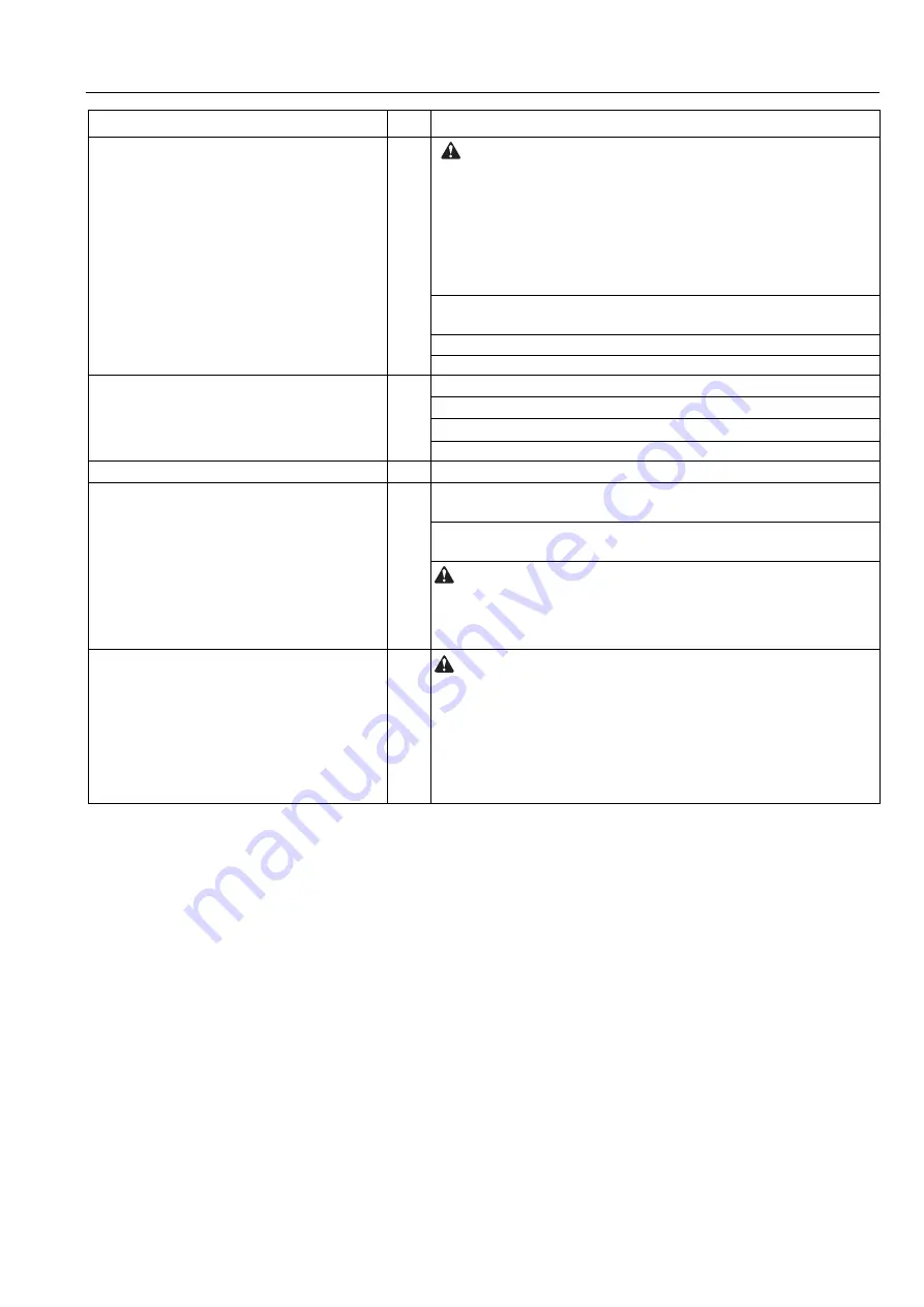
Part name and number in order of its removal
Q’ty
Remarks
1 : Fuel tank
1
WARNING
Gasoline is highly
fl
ammable and its vapors may explode. Pay
attention to following items when working with gasoline.
• Work away from areas having sparks,
fl
ames or other sources
of heat.
• Wipe away any spilled gasoline immediately.
• Work in a well-ventilated area when handling gasoline.
Remove the strainer (5) at the bottom of the throttle lever.
Drain the fuel from the fuel tank by placing the throttle lever (4) in the
"Start" position.
Disconnect the hose (3) from the fuel tank.
Remove the two M8×25 bolts (2) and M8 nuts (9).
4 : Throttle lever
1
Remove the engine side throttle cable (8).
Disconnect the hose (6) from the strainer (5).
Remove the connector (12) for the engine stop switch.
Remove the two M8×16 bolts (7).
11 : Handle
1
Remove the four M8×16 bolts (10).
21 : Engine
1
Loosen the clamp (23) and remove the hose (22) between the
engine and case.
Remove the four M8×25 bolts (15), four M8×30 bolts (16) and two
M8×35 bolts (17). Then remove the engine guards (14) and (24).
CAUTION
Note that the rammer will easily tip over when removing the
engine.
Remove the four M8x35 bolts (13).
20 : Centrifugal clutch
1
WARNING
Do not start the engine with the centrifugal clutch installed.
Starting the engine with the centrifugal clutch installed may
cause the clutch shoe to pop out due to centrifugal force.
Remove the M12 nut (18), centrifugal clutch (20) and half-moon key
(19).
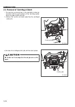
Refer to 2-3. Removal of Centrifugal clutch.
Summary of Contents for RS45
Page 1: ...RS45 RS55E RS65 RS75 SHOP MANUAL 3498 64694 0 ...
Page 2: ......
Page 4: ......
Page 9: ...SAFETY ...
Page 10: ......
Page 17: ...SPECIFICATIONS ...
Page 18: ......
Page 29: ...INSPECTION AND MAINTENANCE ...
Page 30: ......
Page 37: ...PARTS CATALOGUE ...
Page 38: ......
Page 50: ...4 012 PARTS CATALOGUE 2 4 SHOE ASSY 5 6 7 13 12 11 10 9 8 1 2 3 4 16 15 14 17 ...
Page 70: ...4 032 PARTS CATALOGUE 3 4 SHOE ASSY 5 6 13 16 15 14 12 11 10 1 2 3 4 9 8 7 17 ...
Page 76: ...4 038 PARTS CATALOGUE 3 7 NAME PLATE VIEW A A VIEW B B 12 11 2 15 5 9 4 1 3 7 8 10 13 14 ...
Page 92: ...4 054 PARTS CATALOGUE 4 4 SHOE ASSY 8 3 5 4 4 6 5 7 2 1 ...
Page 122: ...4 084 PARTS CATALOGUE 5 4 SHOE ASSY 8 3 5 4 4 6 5 7 2 1 ...
Page 136: ......
Page 137: ...RAMMING SYSTEM ...
Page 138: ......
Page 155: ......


