5-011
RAMMING SYSTEM
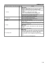
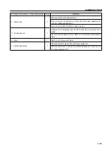
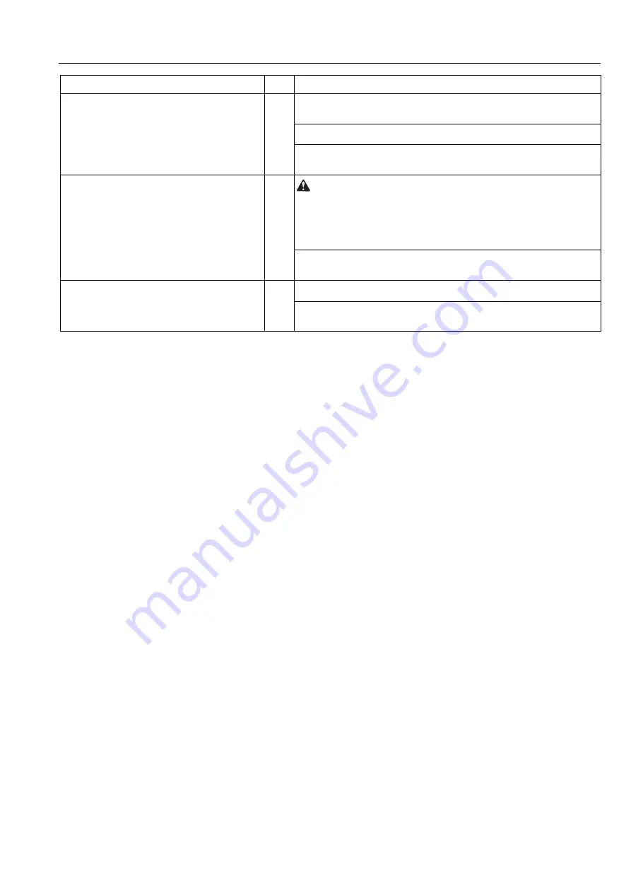
Part name and number in order of its removal
Q’ty
Remarks
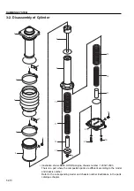
7 : Bellows
1
Remove the two M8 nuts (3). Then remove the upper and lower
clamps (6).
Remove the upper and lower locking pads (2).
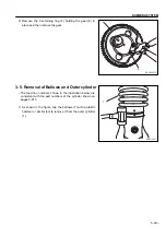
Remove the bellows (7) and outer cylinder (1). Refer to 3-5. Removal
of Bellows and Outer Cylinder.
5 : Oil pan
1
WARNING
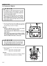
The adapter is under heavy pressure. It must be carefully
removed. If the adapter is removed incorrectly, the springs can
eject with enough force to cause serious injury or death.
Remove the adapter (21). Refer to 3-6 Removal of Adapter.
Remove the stopper (17), inner spring (16), and outer spring (15).
Then remove the oil pan (5).
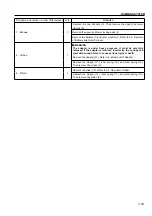
8 : Piston
1
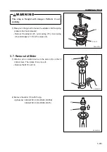
Remove the slider (13). Refer to 3-7. Removal of Slider.
Remove the stopper (12), inner spring (11), and outer spring (10).
Then remove the piston (8).
Summary of Contents for RS45
Page 1: ...RS45 RS55E RS65 RS75 SHOP MANUAL 3498 64694 0 ...
Page 2: ......
Page 4: ......
Page 9: ...SAFETY ...
Page 10: ......
Page 17: ...SPECIFICATIONS ...
Page 18: ......
Page 29: ...INSPECTION AND MAINTENANCE ...
Page 30: ......
Page 37: ...PARTS CATALOGUE ...
Page 38: ......
Page 50: ...4 012 PARTS CATALOGUE 2 4 SHOE ASSY 5 6 7 13 12 11 10 9 8 1 2 3 4 16 15 14 17 ...
Page 70: ...4 032 PARTS CATALOGUE 3 4 SHOE ASSY 5 6 13 16 15 14 12 11 10 1 2 3 4 9 8 7 17 ...
Page 76: ...4 038 PARTS CATALOGUE 3 7 NAME PLATE VIEW A A VIEW B B 12 11 2 15 5 9 4 1 3 7 8 10 13 14 ...
Page 92: ...4 054 PARTS CATALOGUE 4 4 SHOE ASSY 8 3 5 4 4 6 5 7 2 1 ...
Page 122: ...4 084 PARTS CATALOGUE 5 4 SHOE ASSY 8 3 5 4 4 6 5 7 2 1 ...
Page 136: ......
Page 137: ...RAMMING SYSTEM ...
Page 138: ......
Page 155: ......


