Page 9
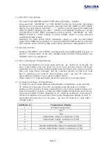
2.4 ON / OFF Timer Setting
The system has ON TIME and OFF TIME setting (Monday – Sunday).
Press and hold
㧎
ON TIMER
㧎
(or “OFF TIMER”) button for 5 seconds, the buzzer
will beep once (long beep) and system will enter into ON TIMER (or OFF TIMER)
setting, the clock display will show “--:--“, and the LCD will show [SET TIME] and
[ON] (or [OFF]) blinking, use “DAY”, “HOUR” and “MINUTE” buttons to set the
unit ON TIME (or OFF TIME), followed by press and hold
㧎
ON TIMER
㧎
(or “OFF
TIMER”) button to confirm setting, or press “CLEAR” button to cancel and exit
unit ON/OFF TIME setting.
Whenever the [ON] and/or [OFF] indicator(s) shown on LCD, the ON TIMER
and/or OFF TIMER is/are enabled. To cancel the ON/OFF TIMER setting, press and
hold “CLEAR” button until the [ON] and/or [OFF] indicator(s) disappeared on LCD.
2.5 Key-lock Function
Pressing “ON TIMER” and “ENTER” simultaneously will enable/disable key-lock. A
symbol “ ” will be shown on the LCD, indicates that all buttons being locked, only
“ON/OFF” button is operational.
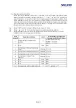
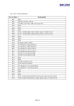
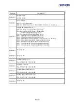
2.6 Error Code Enquiry for Each Module
To check each Module error code, press and hold
㧎
▲
㧎
button for 5 seconds, the
error code display area will show the error code and the buzzer will beep,
meanwhile the unit module number display area will show which module is having
that error code shown. Example: E01 02, meaning module #2 has error code
E01. To check the error code for other modules, press
㧎
▲
㧎
and
㧎
▼
㧎
buttons to
select different module. To exit, press “CLEAR” button.
(Note: Refer error code description section for each error code description)
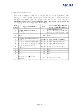
2.7 Temperature Enquiry for Each Module
To check for each module different ambient/water temperature, press and hold
㧎
▼
㧎
button for 5 seconds, the error code display area will show the module
number and the buzzer will beep, meanwhile the unit module number display will
show the respective module
̉
s different ambient/water temperature sub menu (6
sub-menu as listed in table). Example: 02 01, meaning module #2, sub-menu #1
(ambient temperature) is currently shown in the temperature display on LCD. To
select different sub-menu (1 to 6), press
㧎
▲
㧎
and
㧎
▼
㧎
buttons. To exit, press
“CLEAR” button.
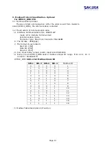
Sub Menu #
Temperature Display
1
Ambient temperature
2
N/A
3
N/A
4
Chilled Water Return Temperature (TH4)
5
Chilled Water
Supply
Temperature (TH5)
6
N/A
7
Overall Chilled Water Return Temperature (TH7)
8
Overall Chilled Water Supply Temperature (TH8)
Summary of Contents for FCA 201
Page 1: ...Ref S FR 266 11 19 Models FCA 201 601 AIR COOLED MODULAR CHILLER ...
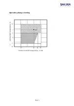
Page 6: ...Page 5 Operating Range Cooling ...
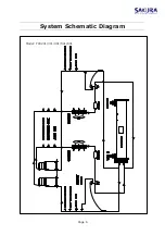
Page 7: ...System Schematic Diagram Page 6 Model FCA201 301 401 501 601 ...
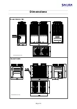
Page 17: ...Dimensions Page 16 Model FCA201 301 Model FCA401 ...
Page 18: ...Page 17 Model FCA501 601 ...
Page 25: ...Page 24 FCA201 301 401 501 601 Maintenance Maintenance ...


