
Due to continued product and information updates, product data sourced from sal.net.au shall not form part of any contract and or technical performance guarantee
unless expressly confirmed in writing by SAL at the time of order.The product wireframe drawings in this document are intended for illustration purposes only and may differ
from the final physical product. The installation instruction is subject to change without prior notice.
SWL600BTAM
Smart Switch G3
Quick Start Guide
Version
Date
2.0
22/06/2023
1. Foreword
IMPORTANT: IN THE INTEREST OF PRODUCT PERFORMANCE AND SAFETY PLEASE READ THESE GUIDE AND WARRANTY INSTRUCTIONS BEFORE INSTALLING THE PRODUCT.
2. Product Introduction
PIXIE Smart Switch G3 is the third generation push button smart switch,
that toggles the ON/OFF status of the load via a single press.
2.1 Product Features
• Fits most branded switch plates
• Fits 1 to 6 gang wall plate installation
• Over temperature protection, overload protection, short circuit
protection
• Complies with Australian and New Zealand Standard: AS/NZS
60669.2.1
• Smart functions via phone/tablet with the SAL PIXIE or PIXIE PLUS APP
• Multiway control - When pairing multiple PIXIE multifunction control
device (e.g. SMF/BTAS) with the same smart Switch, multiway-way
control is achieved
• LED indicator illuminates at high brightness when the switch is on, and
faint when the switch is off, allowing the user to identify the button in the
dark
• LED indicator can be enabled and disabled through the Apps
2.2 The package includes
• PIXIE Smart Switch G3 * 1
• Extra key caps * 2
• Silicon spacer * 1
• Load correction capacitor * 1
• Quick Start Guide * 1
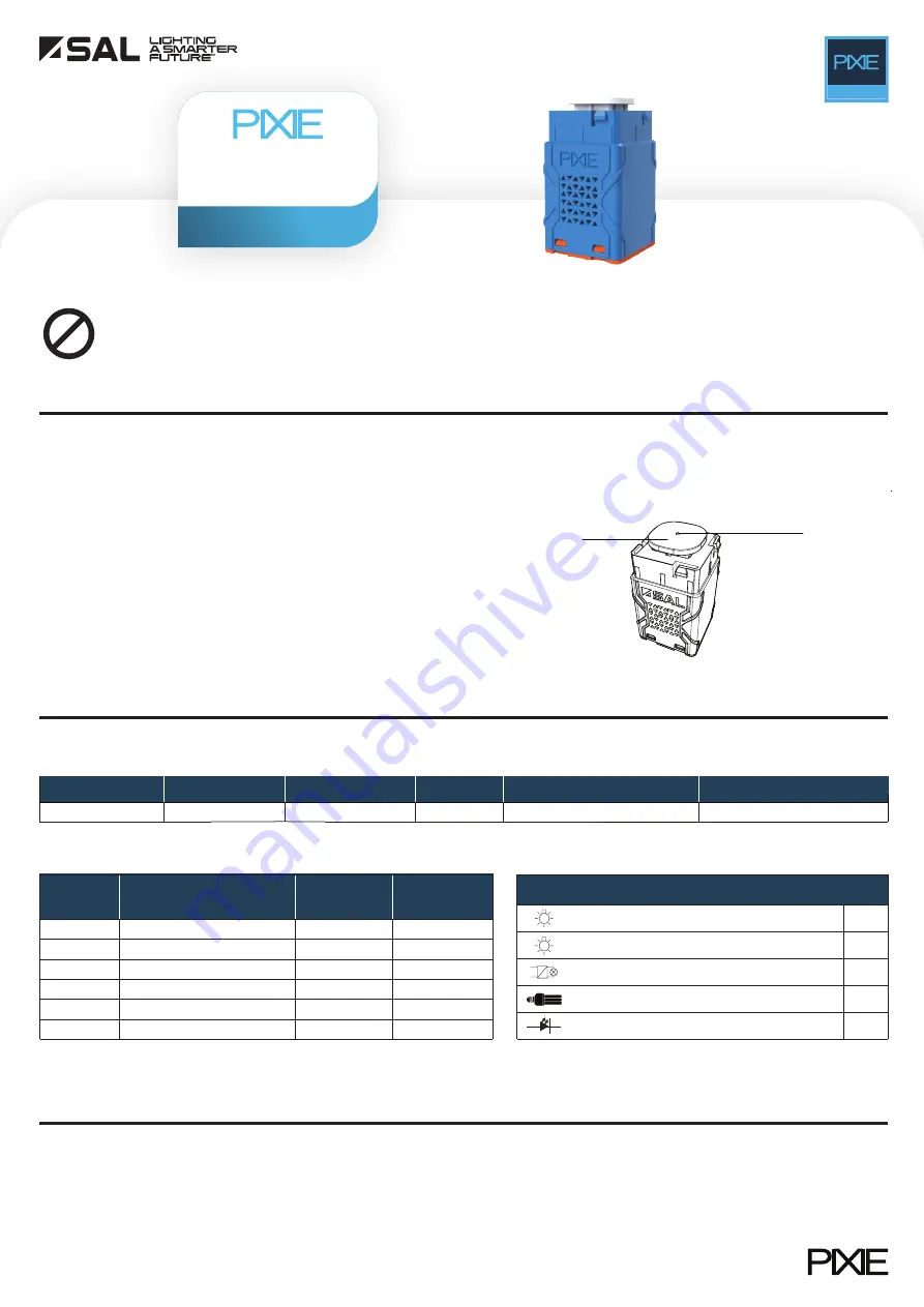
2.3 Product illustration*
3. Specifications
3.1 Basic specifications
3.2 Load rating
3.3 Load compatibility
4. Installation and Wiring
DIY
*All drawings shown are for illustration purpose only, actual product may vary due
to product enhancement.
Installation process
• Make sure the key cap compatibility (pry and replace the default key
cap if necessary)
• Check the load rating and confirm the load compatibility
• Turn OFF the mains electricity supply before commencing installation
• Connect the switch according to the wiring diagram
• Turn ON the mains electricity supply, wait for 10 seconds, then test the
switch operation by pressing the switch button.
LED indicator
Default key cap
(Interchangeable)
Compatible Loads
240V halogen lamp
CFL
Incandescent lamp
Yes
Yes
Yes
Yes
Yes
Low voltage halogen with electronic transformer
LED fixture
No. of switch
Resistive load
(Incandescent/High voltage
halogen lamp)
Capacitive load
(e.g. LED, CFL)
Inductive load
(e.g. exhaust
fan)
1
600W
400VA
250VA
200VA
120VA
100VA
80VA
2
500W
3
500W
4
300W
150VA
150VA
100VA
80VA
60VA
60VA
5
300W
6
200W
*Subject to the load’s electrical characteristics, the load may require the inclusion of a load correction capacitor given in the product carton
Model No.
Input (V)/(Hz)
Dimension L x W x H (mm)
Wireless
Bluetooth Mesh Technology
SWL600BTAM
240/50
9*/600W
Blue
42 x 24 x 24
Colour
Min / Max loads
MASTER
SAL products are designed in accordance with all mandatory International and Australian Standards, which require installation in accordance with AS/NZS3000
by a qualified installer and regular cleaning and maintenance of the equipment. Products are sold in accordance with the following instructions and SAL
standard terms and conditions of sale, available via www.sal.net.au.
Loads with poor electrical performance will apply additional destructive impact to the switch, beyond its rated capabilities, irrespective of power consumption. This
can result on both a shortened lifespan and irreversible damage to this device. This device is not compatible with device below this minimum specification.
-Power Factor < 0.7
-In-rush current > 50A
Caution/Notice


