14
| EN
AMBERAIR COMPACT S-CX v2023.3
4.12. CONNECTING WATER COILS
Only a specially trained employee may connect the air handling unit to the heating or cooling system. When connecting the coil nozzles to the
system, they must be fixed in place with a pipe wrench.
The coil pipes must be connected in such a way that the pipes can be easily accessed during maintenance works. When installing the coil pipes,
make sure that the heat carrier supply is completely disconnected. The coil must be filled with a heat transfer medium before starting the air han
-
dling unit.
Glycol is used in water heat exchangers. Never pour glycol into wastewater, collect it and dispose of it at recycling centres. Glycol is a very dan
-
gerous substance, which may be poisonous even if inhaled in small quantities, avoid contact with the skin and respiratory tract. Keep out of the
reach of children. If you are feeling faint, contact your doctor. Avoid breathing glycol vapour indoors. If glycol gets in your eyes, flush them with
running water (about 5 minutes). Contact your doctor.
When operating the air handling unit in an environment with a temperature lower than 0 °C, it is necessary to use a water-glycol
mixture as the heat carrier or to ensure a return temperature of at least 25 °C.
The heating mixing point must have a circulating pump and a three-way water mixing valve with a modulating actuator. When
using a two-way valve, it is additionally necessary to use a non-return valve to ensure continuous circulation of the heat trans-
fer medium in a small circle. The entire heating mixing point must be installed as close as possible to the coil.
It is important to keep the air heaters and coolers clean, i.e., to change the filters installed in the air handling unit in time, if the
air heater or air cooler becomes dirty it is important to perform their periodic cleaning.
Take care not to damage the water coil when connecting water pipes to connectors.
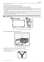
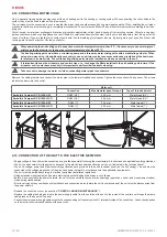
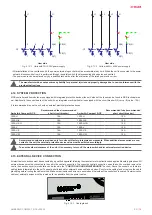
Remove the cable grommet and connect the water pipe to the female threaded connections. Tighten the connection with a spanner. The arrows
indicate the water inlet and outlet.
Water coil
Connection
Max diameter pass-through
Type of threads (in/out)
AmberAir Compact S-CX-1000-V-W
DN20 (3/4”)
26,4 mm
Male thread (3/4”)
AmberAir Compact S-CX-1000-H-CO
DN20 (3/4”)
26,4 mm
Male thread (3/4”)
AmberAir Compact S-CX-1500-V-W
DN25 (1”)
33,4 mm
Male thread (1”)
AmberAir Compact S-CX-1500-H-CO
DN25 (1”)
33,4 mm
Male thread (1”)
4.13. CONNECTION OF THE UNIT TO THE ELECTRIC NETWORK
•
Supply voltage to the unit must be connected by a qualified specialist following the manufacturer’s instructions and applicable safety guidelines.
•
The unit’s power network voltage must correspond to the electro-technical specifications of the unit indicated in the technical decal.
•
The unit’s voltage, power and other technical specifications are provided in the unit’s technical decal (on the unit casing). The unit must be
connected to the voltage plug socket of the grounded power network in accordance with the applicable requirements.
• The unit must be earthed according to electrical equipment installation regulations.
•
Using extension wires (cables) and power network plug socket distribution devices is not allowed.
•
Before it is connected to the power network, the unit must be carefully checked for any damage (operation, control, and measurement nodes)
made during transportation.
•
Prior to carrying out any ventilation unit installation and connection works (before the unit is commissioned), the unit must be disconnected from
the power network.
• Remove the control box cover (see section
).
•
Remove the cable gland plug and route the power supply cable from the outside of the unit to the inside of the control box through the plastic
cable gland on the upper unit’s panel.
•
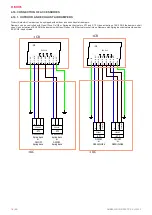
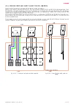
Connect securely power supply cable wires to the corresponding unit’s safety switch Q1 terminals inside of the control box. Connection depends
on the electro-technical specifications of the exact unit.


