EN |
17
AMBERAIR COMPACT S-CX v2023.3
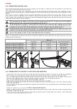
4.16.2. FIRE AND FIREPLACE SAFETY (SAFETY INPUTS, DAMPERS)
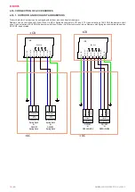
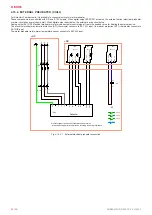
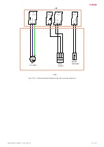
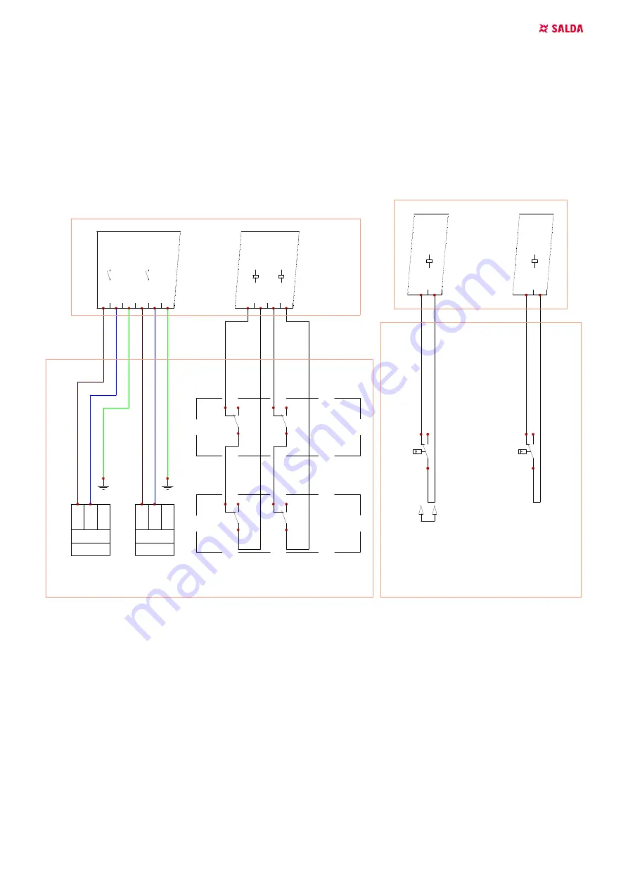
Product AmberAir Compact can be equipped with fire dampers for extract and supply air.
Dampers are controlled by Spring-return actuators (A1, A2). Upon activation of signals EX2 DO1 and EX2 DO2 the dampers shall open. When
EX2 DO1/DO2 is deactivated, the dampers shall close. Fire dampers must be equipped with damper position switches. When the dampers
completely close, the switches K6/K8 should be activated. When the dampers are completely open, switches K5/K7 should be activated. MCB
controller can be configured to operate with NO or NC switches.
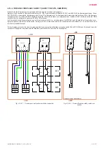
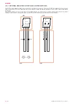
For fire safety function it is available to connect the external switch FA (i.e., smoke detector) to MCB DI4 input. By default, unit’s controller is con
-
figured to operate with NC fire safety switch. As long as the fire protection device is not connected to the ventilation unit, on an input there must
be a factory-installed jumper.
For the fireplace protection function, it is also possible to connect external fireplace protection switch FAA to MCB DI8 input. By default, the unit’s
controller is configured to operate with NO fireplace protection switch and it can be reconfigured.
DRAWN BY
CHECKED BY
SIGNATURE
DUTIES / NAME
DATE
UAB"SALDA"
Drawing #
Book #
APPROVED BY
1
2
3
4
5
6
7
8
9
10
EI O. Drąsutis
EI D. Aleksandravičius
MCB Connections wired by the user
Air dampers (Electrical unit)
Connections principal scheme
1
02
2023-03-27
2023-03-27
2023-03-27
X32:
1
- D
O1
X32:
2
- N
(L
1)
X32:
3
- P
E
X32:
4
- D
O2
X32:
5
- N
(L
1)
X32:
6
- P
E
-N3
EX2 V1.0
230V ON/OFF
Spring back
L
-s
up
ply
N
-A1
230V ON/OFF
Spring back
L
-s
up
ply
N
-A2
X23:
1
- D
I9
X23:
2
- +1
2V
DC
X23:
3
- D
I1
0
X23:
4
- +1
2V
DC
-N2
EX1 V2.0
-K5
NC NO
COM
-K7
NC NO
COM
-K6
NC NO
COM
-K8
NC NO
COM
X35:
1
- P
E
X35:
2
- N
(L
1)
X35:
3
- D
O5
X35:
4
- D
O6
X35:
5
- D
O5
X35:
6
- D
O6
X35:
7
- N
(L
1)
X35:
8
- P
E
-N3
EX2 V1.0
230VAC
N
L-
su
pp
ly
L-c
on
tro
l
-ST1
230VAC
N
L-
su
pp
ly
L-c
on
tro
l
-ST2
A1
A2
+CB
+UC
+CB
+UC
ON/OFF
or
OPEN/CLOSE
ON/OFF
or
OPEN/CLOSE
DRAWN BY
CHECKED BY
SIGNATURE
DUTIES / NAME
DATE
UAB"SALDA"
Drawing #
Book #
APPROVED BY
1
2
3
4
5
6
7
8
9
10
EI O. Drąsutis
EI D. Aleksandravičius
MCB Connections wired by the user
Digital inputs and outputs
Connections principal scheme
1
03
2023-03-27
2023-03-27
2023-03-27
X27:
1
- I
ND
_1
X27:
2
- +2
4V
DC
X27:
3
- I
ND
_2
X27:
4
- +2
4V
DC
-N2
EX1 V2.0
X21:
5
- D
I3
X21:
6
- +1
2V
DC
X21:
7
- D
I4
X21:
8
- +1
2V
DC
-N2
EX1 V2.0
24VDC
max. 50mA
1.2W
24VDC
max. 50mA
1.2W
-START
-STOP
-S
ys
te
m
mod
e
sw
itc
h
-F
an
s
pe
ed
sw
itc
h
+CB
+UC
+CB
+UC
-FPP
NC
NO
COM
-FA
NC
NO
COM
Jumper*
*Jumper wired by manufacturer
+CB
+UC
X4
:1
- D
I4
X4
:2
- +
12
VD
C
-N1
MCB V1.0
X2
2:
7 -
D
I8
X2
2:
8
- +
12V
DC
-N2
EX1 V1.0
Fig. 4.16.2.1 Fire dampers and position switches connection
Fig. 4.16.2.2
Fire and fireplace safety switch con
-
nection


