24
| EN
AMBERAIR COMPACT S-CX v2023.3
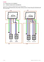
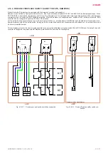
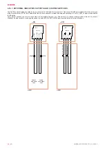
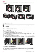
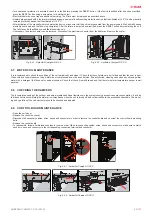
4.16.7. EXTERNAL INDICATION OUTPUTS AND CUSTOM SWITCHES
Two 24VDC external indication outputs can be connected to the AmberAir Compact unit. One output (START) is to indicate that the unit is oper
-
ating. Another output (STOP) is to indicate that the unit encountered a problem and stopped operating. EX1 IND_1/IND_2 outputs are dedicated
for indication.
Two external switches can also be connected to the AmberAir Compact unit. One switch is to change working mode of the unit (by default
Standby). Another switch is to change fan speed (by default 100%) EX1 DI3/DI4 inputs are dedicated to external switches.
DRAWN BY
CHECKED BY
SIGNATURE
DUTIES / NAME
DATE
UAB"SALDA"
Drawing #
Book #
APPROVED BY
1
2
3
4
5
6
7
8
9
10
EI O. Drąsutis
EI D. Aleksandravičius
MCB Connections wired by the user
Digital inputs and outputs
Connections principal scheme
1
03
2023-03-27
2023-03-27
2023-03-27
X27:
1
- I
ND
_1
X27:
2
- +2
4V
DC
X27:
3
- I
ND
_2
X27:
4
- +2
4V
DC
-N2
EX1 V2.0
X21:
5
- D
I3
X21:
6
- +1
2V
DC
X21:
7
- D
I4
X21:
8
- +1
2V
DC
-N2
EX1 V2.0
24VDC
max. 50mA
1.2W
24VDC
max. 50mA
1.2W
-START
-STOP
-S
ys
te
m
mod
e
sw
itc
h
-F
an
s
pe
ed
sw
itc
h
+CB
+UC
+CB
+UC
-FPP
NC
NO
COM
-FA
NC
NO
COM
Jumper*
*Jumper wired by manufacturer
+CB
+UC
X4
:1
- D
I4
X4
:2
- +
12
VD
C
-N1
MCB V1.0
X2
2:
7 -
D
I8
X2
2:
8
- +
12V
DC
-N2
EX1 V1.0


