EN |
51
AMBERAIR COMPACT S-CX v2023.3
DATE
SIGNATURE
DRAWN BY
DUTIES / NAME
SALDA UAB
CHECKED BY
APPROVED BY
Drawing #
Book #
REVISION
9
3
2
1
10
8
6
7
4
5
1
2
5
4
3
P&I diagram
3
IE G. Remeika
Plate-HRU Horizontal Right CO
04
2023-07-17
2023-07-17
A
+
-
-
+
+
-
+
-
Coil1
PS1
U3(p)*
-
+
+
-
C
-EHA
ST1
ODA
A2
A1
ST2
Coil1
SUP
Coil2
Coil2
EHA
M3
Duct
Air handling unit
AQS
Duct
SAF
U3(f)
-
+
PS2
ETA
-
+
U4(f)
EAF
+
-
+
-
0-10V sensors:
- CO2
- RH
U4(p)*
OF
EF
* U3(p) and U4(p) are converted from U3(f) and U4(f) to control fan speed by constant air pressure
-ODA
M6
P6
WTO6
PE3
HW3
OR
Coil3
Coil3
+
-
-
+
PS3
CW1
M1
P1
WTO1
HW2
M5
P5
WTO5
-ETA
-SUP
AQS 0-10V
sensors:
- CO2
- RH
With MB - GATEWAY:
- SALDA AIR
- Web interface
- BMS over Modbus TCP/IP
- BMS over BACnet IP
Room
Remote control panels:
- ST- SA control
- Stouch
DX2
T3
T1
T2
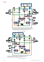
Fig. 8.6.2 Horizontal right units with integrated combined heating/cooling coil
DATE
SIGNATURE
DRAWN BY
DUTIES / NAME
SALDA UAB
CHECKED BY
APPROVED BY
Drawing #
Book #
REVISION
9
3
2
1
10
8
6
7
4
5
1
2
5
4
3
P&I diagram
3
IE G. Remeika
Plate-HRU Horizontal Left E/empty
05
2023-07-17
2023-07-17
A
Air handling unit
Duct
Room
-ETA
AQS
0-10V sensors:
- CO2
- RH
A2
A1
Coil2
SUP
Coil2
+
-
+
-
U4(p)*
C
PS2
+
+
-
-
ETA
U3(p)*
+
+
-
-
-
+
SAF
U3(f)
Coil1
Coil1
HE1
OR Without
Coil1
Duct
M3
PS1
-
-
+
+
ODA
EHA
-
+
U4(f)
EAF
ST1
ST2
-EHA
OF
EF
* U3(p) and U4(p) are converted from U3(f) and U4(f) to control fan speed by constant air pressure;
-ODA
-SUP
CW2
M4
P4
WTO4
Coil3
M6
P6
WTO6
PE3
HW3
OR
Coil3
PS3
+
+
-
-
AQS 0-10V
sensors:
- CO2
- RH
With MB - GATEWAY:
- SALDA AIR
- Web interface
- BMS over Modbus TCP/IP
- BMS over BACnet IP
Remote control panels:
- ST- SA control
- Stouch
T4
DX2
T3
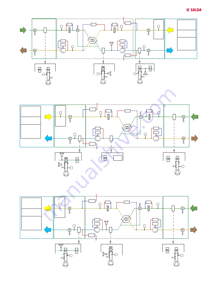
Fig. 8.6.3 Horizontal left units with integrated electrical heater or without integrated heater/cooler
DATE
SIGNATURE
DRAWN BY
DUTIES / NAME
SALDA UAB
CHECKED BY
APPROVED BY
Drawing #
Book #
REVISION
9
3
2
1
10
8
6
7
4
5
1
2
5
4
3
P&I diagram
3
IE G. Remeika
Plate-HRU Horizontal Left CO
06
2023-07-17
2023-07-17
A
Air handling unit
Duct
Room
-ETA
AQS
0-10V sensors:
- CO2
- RH
A2
A1
Coil2
SUP
Coil2
+
-
+
-
U4(p)*
C
PS2
+
+
-
-
ETA
U3(p)*
+
+
-
-
-
+
SAF
U3(f)
Coil1
Coil1
Duct
M3
PS1
-
-
+
+
ODA
EHA
-
+
U4(f)
EAF
ST1
ST2
-EHA
OF
EF
* U3(p) and U4(p) are converted from U3(f) and U4(f) to control fan speed by constant air pressure;
-ODA
-SUP
DX2
Coil3
M6
P6
WTO6
PE3
HW3
OR
Coil3
PS3
+
+
-
-
AQS 0-10V
sensors:
- CO2
- RH
With MB - GATEWAY:
- SALDA AIR
- Web interface
- BMS over Modbus TCP/IP
- BMS over BACnet IP
Remote control panels:
- ST- SA control
- Stouch
HW2
M5
P5
WTO5
CW1
M1
P1
WTO1
T3
T1
T2
Fig. 8.6.4 Horizontal left units with integrated combined heating/cooling coil

