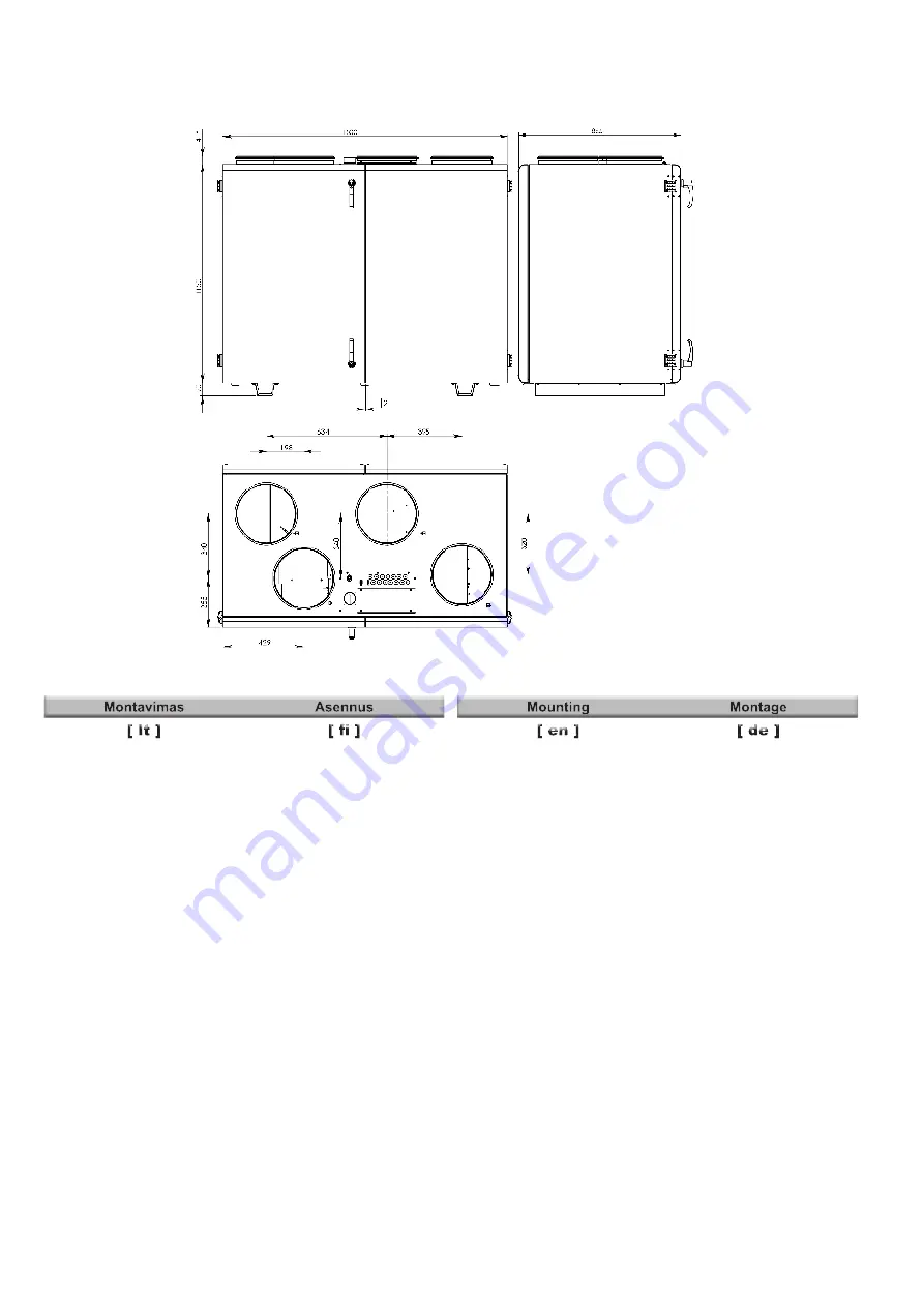
- Montavimo darbus turėtų atlikti tik patyrę ir ap-
mokyti darbuotojai.
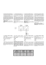
- Įrenginį būtina sumontuoti ant lygaus hori-
zontalaus paviršiaus taip, kad gaminys nebūtų
pasviręs (pav 01).
- Prieš pajungiant į ortakių sistemą, vėdinimo
įrenginio ortakių pajungimo angas reikia ati-
dengti .
- Esant poreikiui yra numatyta galimybė pa-
keisti aptarnavimo pusę.
- Prijungdami ortakius, atkreipkite dėmesį į oro
srauto kryptis, nurodytas ant įrenginio korpuso.
- Nejunkite alkūnių arti įrenginio pajungimo
flanšų. Minimalus atstumas tiesaus ortakio tarp
įrenginio ir pirmo ortakių atsišakojimo oro įsiur-
bimo kanale turi būti 1xD, oro išmetimo kanale
3xD, kur D- ortakio diametras.
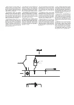
- Jungiant ventiliatorių į ortakių sistemą, pata-
riame naudoti priedus- apkabas (pav 02). Tai
sumažins įrenginio perduodamus virpesius į
ortakių sistemą ir aplinką.
- Būtina sumontuoti taip, kad ortakių sistemos
ir jos visų komponentų svoris neapkrautų vėdi-
nimo įrenginio.
- Montuojant būtina palikti pakankamai vietos
vėdinimo įrenginio aptarnavimo durelėms ati-
daryti.
- Jei sumontuotas vėdinimo įrenginys yra pri-
glaustas prie sienos, tai gali perduoti triukšmo
vibracijas į patalpą, nors ir ventiliatorių suke-
liamas triukšmo lygis yra priimtinas. Patariame
montuoti 400 mm atstumu nuo artimiausios sie-
nos. Jei tai nėra įmanoma, patariame montuoti
prie sienos su patalpa, kuriai keliamas triukš-
mas nėra svarbus.
- Taip pat vibracijos gali būti perduodamos per
grindis. Jei yra tokia galimybė, būtina papil-
domai izoliuoti grindis, kad nuslopinti keliamą
triukšmą.
- Vamzdynai prie šildytuvo jungiami taip, kad
atliekant aptarnavimo ir remonto darbus, vamz-
dynus būtų galima greitai išmontuoti ir išimti
šildytuvą iš įrenginio korpuso.
- Vamzdynai su tiekiamais ir grįžtamais šilumos
nešėjais turi būti prijungiami taip, kad šildytuvas
- Asennuksen saavat tehdä vain pätevät ja koulutetut
työntekijät.
- Laite on asennettava tasaiselle ja vaakasuoralle
tasolle (kuva 01).
- E n n e n k a n a v i s t o o n k y t k e m i s t ä
ilmanvaihtojärjestelmän ilmakanavien liitäntäaukot
on suljettava.
- Tarvittaessa huoltopuoli voidaan vaihtaa.
- Kytkettäessä ilmakanavia on huomioitava laitteen
koteloon merkityt ilmanvirtaussuunnat.
- Mutkakohtia ei saa kytkeä lähellä laitteen
l i i t ä n t ä l a i p p o j a . S u o r a n i l m a k a n a v a n
vähimmäisetäisyyden laitteen ja imuilmakanavan
ilmakanavan ensimmäisen haaran välillä tulee
olla 1 × D ja ilmanpoistokanavassa 3 × D, jossa
D on ilmakanavan halkaisija. Suorakulmaiset
ilmakanavat: jossa B = ilmakanavan leveys ja H =
ilmakanavan korkeus.
- Asennus on tehtävä niin, että kanaviston ja sen
osien paino ei ylikuormita ilmanvaihtokonetta.
- Asennuksen aikana on jätettävä riittävästi tilaa
ilmanvaihtokoneen huoltoluukun avaamista varten.
- Jos asennettu ilmanvaihtokone on kiinni seinässä,
se saattaa välittää meluvärähtelyä tiloihin, vaikka
puhaltimien aiheuttama melutaso on hyväksyttävä.
Asennettaessa on suositeltavaa jättää 400 mm:n
etäisyys lähimpään seinään. Jos tämä ei ole
mahdollista, laite kannattaa asentaa huoneessa
sellaisen seinän viereen, joka ei ole melutason
kannalta merkityksellinen.
- Värähtelyä saattaa siirtyä myös lattian läpi. Melua
on vaimennettava mahdollisuuksien mukaan myös
tärinänvaimennusalustoilla.
- Putket kytketään lämmittimeen niin, että ne voidaan
purkaa helposti ja lämmitin voidaan irrottaa laitteen
kotelosta huolto- tai korjaustöiden ajaksi.
- Putket, joissa on tulo- ja paluulämpökuljettimet, on
kytkettävä niin, että lämmitin toimisi vastakkaiseen
suuntaan ilmavirtaan nähden. Jos lämmitin toimii
käyttämällä samoja suuntia, keskilämpötilan ero
laskee, mikä vaikuttaa lämmittimen tehokkuuteen.
- Kone on suojattava kastumiselta.
- Installing should only be performed by qualified
and trained staff.
- The unit must be mounted on the flat horizontal
surface so tas not to lean (Pic. 01).
- Before connecting to the air duct system, the
connection openings of ventilation system air
ducts must be opened.
- If necessary, the maintenance side can be
changed.
- When connecting air ducts, consider the air
flow directions indicated on the casing of the unit.
- Do not connect the duct elbows in vicinity of
the connection flanges of the unit. The minimum
distance of the straight air duct between the unit
and the first branch of the air duct in the suction
air duct must be 1xD, in air exhaust duct 3xD,
where D is diameter of the air duct.
- It is recommended to use the accessories-
holders (Pic. 02) for connection of the fan to
the air duct system. This will reduce vibration
transmitted by the unit to the air duct system
and environment.
- Installation must be performed in such manner
that the weight of the air duct system and its com-
ponents would not overload the ventilation unit.
- Enough space must be left during installation
for opening of the maintenance door of the
ventilation unit.
- If the installed ventilation unit is adherent to
the wall, it may transmit noise vibrations to the
premises even though the level of noise caused
by the fans is admissible. The installation is rec-
ommended at the distance of 400 mm from the
nearest wall. If it is not possible, the installation
of the unit is recommended by the wall of the
room where the level of noise is not important.
- Also, vibrations can be transmitted through the
floor. If possible, additionally insulate the floor to
suppress the noise.
- Pipes are connected to the heater in such way
that they could be easily disassembled and the
heater could be removed from the unit casing
when performing service or repair works.
- Pipes with supply and return heat carriers must
be connected in such way that the heater would
work in the opposite direction for the air flow. If
- Die Montage darf nur durch ausgebildetes
und eingewiesenes Fachpersonal durchgeführt
werden.
- Das Gerät ist auf einer ebenen und horizontalen
Oberfläche nicht geneigt zu montieren (Bild 01).
- Vor dem Anschließen an das Luftleitungssystem
sind Luftleitungen Anschluss öffnen.
- Bei Bedarf besteht die Möglichkeit, die Wartungs-
seite zu ändern.
- Beim Anschließen der Luftleitungen ist auf die am
Gerätegehäuse angegebenen Luftströmungsrich-
tungen zu achten.
- Schließen Sie keine Bögen in der Nähe von Gerä-
teanschlussstutzen an. Der Mindestabstand einer
geraden Luftleitung zwischen dem Gerät und der
ersten Abzweigung in der Zuluftleitung muss 1xD,
in der Abluftleitung 3xD betragen (D - Durchmesser
der Luftleitung).
- Beim Anschließen des Ventilators an das Luftlei-
tungssystem empfehlen wir, Zusatzkomponenten
- Flexibele Verbindung - zu verwenden (Bild 02).
Dies verringert die vom Gerät an das Luftlei-
tungssystem und die Umgebung übertragenen
Schwingungen.
- Die Montage ist so durchzuführen, dass durch
das Gewicht des Luftleitungssystems und aller
seiner Bauteile keine Belastungen am Lüftungs-
gerät auftreten.
- Bei der Montage ist ein ausreichender Schwenk-
bereich für die Wartungstür des Lüftungsgerätes
vorzusehen.
- Wird das Lüftungsgerät dicht an der Wand
montiert, können dadurch die Schallvibrationen
in den Raum übertragen werden, auch wenn
der Geräuschpegel der Ventilatoren akzeptabel
ist. Es ist zu empfehlen, die Montage in einem
Abstand von 400 mm zur nächstgelegenen Wand
durchzuführen. Ist dies nicht möglich, empfehlen
wir die Montage an einer Wand zu einem Raum,
für den der Lärm nicht wichtig ist.
- Die Schwingungen können auch über die Fußbö-
den übertragen werden. Besteht diese Möglichkeit,
sollten die Fußböden zusätzlich isoliert werden, um
den Lärm abzudämpfen.
- Die Rohrleitungen sind am Heizregister so anzu-
schließen, dass sie bei Wartungs- und Instandset-
RIRS 1200 VL EKO 3.0
Summary of Contents for RIRS 1200VW EKO 3.0
Page 26: ......


