background image

18 

| EN

RIRS 1200-5500 H EKO 3.0 v2019.06

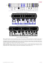
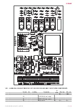
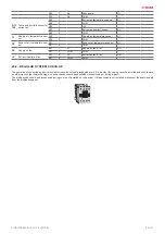
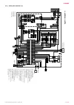
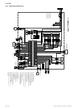
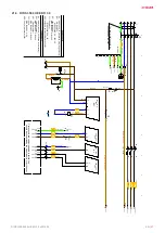
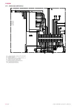
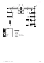
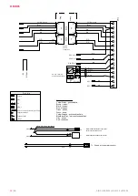
20. CONTROL BOARD RG1

LED indications of the controller Pic. 3a

LED2

Air damper close

LED9

Medium fans speed

LED2 + LED3

Air damper open

LED10

Minimal fans speed

LED4

Water valve open

LED11

Supply air fan speed reducing

LED5

Water valve close

LED12

Preheater

LED6

BYPASS open

LED13

Supply air heater

LED7

BYPASS close

LED14

Circulator pump

LED8

Maximal fans speed

Summary of Contents for RIRS EKO 3.0 1200 HE

Page 1: ...RIRS 1200 5500 H EKO 3 0 EN MOUNTING AND INSTALLATION INSTRUCTION ...

Page 2: ...ERS 11 18 2 FAN 11 18 3 HEAT EXCHANGER 12 18 4 ELECTRICAL HEATER 13 19 AUTOMATIC CONTROL 13 19 1 SYSTEM PROTECTION 14 19 2 USING THE UNIT IN BMS NETWORK 14 19 3 MODBUS ADRESSES 15 19 4 ELECTRICAL CONNECTION OF THE HVAC UNIT 16 19 5 SYSTEM ADJUSTMENT GUIDELINES 16 20 CONTROL BOARD RG1 18 20 1 LABELING CHARACTERISTICS OF THE CONTROLLER AND THE SYSTEM COMPONENTS 19 20 2 REGULAR SYSTEM CHECK UP 21 21 ...

Page 3: ...frequency Max current Max power consumption Protection class Weight xxx xx VAC Hz x xx A x xx kW IP xx xx kg Made in Šiauliai Lithuania AHU000000 BN xxxxxx 2019 01 01 SERIAL 2514523357 XXX GAMINIO PAVADINIMAS Nominal voltage frequency Max current Max power consumption Protection class Weight xxx xx VAC Hz x xx A x xx kW IP xx xx kg Made in Šiauliai Lithuania AHU000000 BN xxxxxx 2019 01 01 Figure 2...

Page 4: ...da Antifrost system uses dis balancing of the air flow and it may cause negative pressure in premises Great care should be taken when using at the same time in premises as another heating appliance what depend on the air in premises Such appliances include gas oil wood or coal fired boilers and heaters fireplaces continuous flow or other water heaters gas hobs cookers or ovens which draw air in fr...

Page 5: ...0 715 3 1 0 715 3 1 1 3 6 4 1 3 6 4 speed min 1 2800 2800 2390 2390 supply power current kW A 0 715 3 1 0 715 3 1 1 31 6 4 1 3 6 4 speed min 1 2800 2800 2390 2390 control input VDC 0 10 0 10 0 10 0 10 protection class IP 54 IP 54 IP54 IP54 Total power consumption power current kW A 10 47 19 61 1 48 6 46 14 64 30 52 2 64 13 18 Automatic control integrated Thermal efficiency 83 6 84 5 80 80 Insulati...

Page 6: ...er 6 Control board 7 Extract air filters panel pocket 8 Supply air filter panel pocket 9 Rotor engine 7 OPERATING CONDITIONS 5 C o 40 C o 40 C o 40 C o 15 C o 40 C o 3 C o 40 C o 5 C o 40 C o 23 C o 40 C o 15 C o 40 C o 40 C 23 C o O 40 C 15 C O O RH 60 40 C 23 o C O Ex 40 C 5 C O O 40 C 15 C O O RH 60 40 C 40 C O O Ex 40 C 40 C O O o 40 C o 8 PACKAGE H L W RIRS H EKO 3 0 H W L QUANTITY ON THE PAL...

Page 7: ...the unit first unpack the accessories Remove the film from the unit Remove the bracing packaging tape which keeps the protective profiles Remove the protective profiles After unpacking the unit examine it to make sure that it it has not been damaged during transportation The installation of damaged units is prohibited Verify that all ordered equipment are delivered before starting the installation...

Page 8: ...REQUIREMENTS L 1 5xL L 1 5xL H Min distance to open the door 1 5xL Min distance to open control box door H 400 mm 13 MOUNTING The protective film is intended to protect the unit during transportation It is recommended to remove the film because other wise oxidation signs may occur Before every heating season the condensate tube shall be filled with water as indicated during the first startup W α W...

Page 9: ...ECTION OF THE AIR DUCT Figure 14 1 Circular air duct conection Figure 14 2 Rectangular air duct conection 15 CONNECTION DIAGRAM PS PS PS PS PS 2 2 2 2 2 Figure 15 1 RIRS 1200 1900 HE EKO 3 0 Placement of the component depends on model PS Figure 15 2 RIRS 1200 1900 HW EKO 3 0 ...

Page 10: ...mostat KV2 Water pre heater TV2 Water preheater temperature sensor KV3 Water cooler TV3 Water cooler temperature sensor DX DX cooler U3 PV pressure transmitter M1 By pass damper U4 IV pressure transmitter M2 Outdoor air damper actuator CO2 CO2 sensor M3 Exhaust air damper actuator RH RH sensor M5 Water cooler valve motor PC Computer M12 Water pre heater valve actuator RC2 Stouch Flex or SA Control...

Page 11: ... power connection diagrams all electrical equipment protection elements are properly connected if they are additionally used cables and wires correspond to all applicable safety and functional requirements diameters etc earthing and protection systems are properly installed condition of all seals and sealing surfaces are proper 17 2 POSSIBLE FAULTS AND TROUBLESHOOTING FAILURE CAUSE EXPLANATION COR...

Page 12: ... cause disbalance of impeller or damage it Hold the fan by the casing Figure 18 1 RIRS 1200 1900 H EKO 3 0 Figure 18 2 RIRS 2500 5500 H EKO 3 0 18 3 HEAT EXCHANGER Be sure the unit is disconnected from power source before performing any maintenance or repair Proceed to maintenance and repair after any rotation in the fan stopped Clean it once a year The maintenance works for the rotor heat exchang...

Page 13: ...d by the ESKM controller using the PWM signal If the water supply air heater is used then the actuator is controlled using RG1 controller with analogous 0 10V DC signal BOOST feature Fans are started at maximum speed and BOOST is displayed in the remote control panel FLEX BOOST feature is inactive if the heat ex changer protection is triggered When triggering signal for this function disappears th...

Page 14: ...pes of the capillary thermal protections are used for the overheat protection of the electrical heater manual and automatic Automatic thermal protection is activated when air temperature exceeds 50 C and manual protection is activated when air temperature exceeds 100 C Automatic thermal protection 50 C is used to disconnect the electric heater if the temperature of the heating elements exceeds 50 ...

Page 15: ...1 Supply air temperature sensor alarm 1 a c t i v e o passive 9 RH 01h_Read_Coils 9 1 TJ 100 humidity sensor alarm controller works in deter mining the moisture content of 70 1 a c t i v e o passive 10 ReturnWater 01h_Read_Coils 10 1 Return water temperature sensor alarm 1 a c t i v e o passive 11 ToutDoor 01h_Read_Coils 11 1 Outside air temperature sensor alarm controller continues to work in det...

Page 16: ... should be used Connect the plug RJ10 type to the RS485 1 socket of the unit Connect the other end to the control panel RS458_1 RS458_2 NOTE The remote control panel can be connected and or disconnected only after disconnecting the power supply for the HVAC unit Switch on the mains voltage switch on the blade switch Q see Fig 5 actual appearance of the blade switch can be different from the given ...

Page 17: ... 24VAC G System potential 24VAC 24VAC 3 position M5 G Y2 Y1 Water cooler valve actuator Jumper STOP NO START NC BOOST CE7 7 X16 7 PE N L1 L1 N PE L1 N PE L1 N PE 1f 230V AC Power supply cable X16 36 36 28 25 20 22 23 24 24 23 22 23 24 X16 4 25 25 31 30 X16 7 29 34 33 32 35 36 30 29 31 33 32 34 35 27 26 28 30 29 31 33 32 34 35 27 26 28 26 27 X16 10 15 18 17 X16 5 19 17 15 14 13 12 11 22 21 11 12 13...

Page 18: ...3a LED2 Air damper close LED9 Medium fans speed LED2 LED3 Air damper open LED10 Minimal fans speed LED4 Water valve open LED11 Supply air fan speed reducing LED5 Water valve close LED12 Preheater LED6 BYPASS open LED13 Supply air heater LED7 BYPASS close LED14 Circulator pump LED8 Maximal fans speed ...

Page 19: ...019 06 20 1 LABELING CHARACTERISTICS OF THE CONTROLLER AND THE SYSTEM COMPONENTS Contact No Labeling Description I O type Max load Min load A mA X10 L 230V 50Hz power supply I X8 N 230V 50Hz power supply I X31 Electric heater O 16A 100 ...

Page 20: ... AO X33 5 VAL Cooling valve common Pulse 24v 50hz AO M1 By pass actuator X33 6 DMP Bypass damper opening PWM 24v 50hz AO 100mA X33 7 DMP By Pass damper closing PWM 24v 50hz AO 100mA X33 8 DMP By Pass damper common PWM 24v 50hz AO 100mA DX DX cooler or water heater cir culatory pump control X33 9 CHIL DX cooling ON OFF 24V DO 0 05mA X33 10 COM COM X33 11 ALARM Indicates when fans fail ON OFF 24V DO...

Page 21: ...41 2 COM PV Supply air fan X37 1 V1 Supply air fan 0 10V AO X37 2 COM COM IV Extract room s air fan X37 3 V2 Extract air fan 0 10V AO X37 4 COM COM 20 2 REGULAR SYSTEM CHECK UP The operation of the switching device contactor should be visually inspected every 3 4 months the casing cannot be melted and should have no other signs of the thermal damage no extra sounds should be generated while switch...

Page 22: ...33 2 CHIL X33 9 COM X33 10 BOOST STOP NO START NC A2 A1 R1 8 7 X16 3 ALARM X33 11 COM ANTI F Fan fall 1 2W max 4 5 6 10 9 X16 4 24 1 2W max Fan run 11 12 COM FAN 25 24 23 24V DC 24 intput 0 10V DC 25 GND Transmitter 1 24 VDC U P 23 X29 X25 N L 3 1 P DX Cooling PS2 PS1 2 1 8 7 6 5 B 0 10 COM 14 11 G M5 24VAC 3 position Y2 Y1 VAL VAL VAL X33 3 X33 4 X33 5 3 1 2 X16 1 24VDC Y1 Control OPEN AC 24 V Y2...

Page 23: ... A1 R1 8 7 X16 3 ALARM X33 11 COM ANTI F Fan fall 1 2W max 4 5 6 10 9 X16 4 24 1 2W max Fan run 11 12 COM FAN 25 24 23 24V DC 24 intput 0 10V DC 25 GND Transmitter 1 24 VDC U P 23 X29 X25 N L 3 1 P DX Cooling PS2 PS1 2 1 8 7 6 5 B 0 10 COM 14 11 G M5 24VAC 3 position Y2 Y1 VAL VAL VAL X33 3 X33 4 X33 5 3 1 2 X16 1 24VDC Y1 Control OPEN AC 24 V Y2 Control CLOSE AC 24 V G System potential AC 24 V X3...

Page 24: ... 230V AC 230V AC ON OFF ON OFF L X37 TL LOW X32 1 COM X32 4 HIGH X32 2 TIMER X32 3 COM X33 1 MIDL X33 2 CHIL X33 9 COM X33 10 BOOST STOP NO START NC A2 A1 R1 8 7 X16 3 ALARM X33 11 COM ANTI F Fan fall 1 2W max 4 5 6 10 9 X16 4 24 1 2W max Fan run 11 12 COM FAN 25 24 23 24V DC 24 intput 0 10V DC 25 GND Transmitter 1 24 VDC U P 23 X29 X25 N L 3 1 P DX Cooling PS2 PS1 2 1 8 7 6 5 B 0 10 COM 14 11 G M...

Page 25: ...control RG1 FA 13 14 16 15 X16 6 TL LOW X32 1 COM X32 4 HIGH X32 2 TIMER X32 3 COM X33 1 MIDL X33 2 CHIL X33 9 COM X33 10 BOOST STOP NO START NC A2 A1 R1 8 7 X16 3 ALARM X33 11 COM ANTI F Fan fall 1 2W max 4 5 6 10 9 X16 4 24 1 2W max Fan run 11 12 COM FAN 19 18 17 24V DC 18 intput 0 10V DC 19 GND Transmitter 1 24 VDC U P 17 X29 X25 N L 3 1 P DX Cooling B 0 10 COM 14 11 G M5 24VAC 3 position Y2 Y1...

Page 26: ...K TJ tiekiamo oro temperatūros jutiklis TJK 10K TE išmetamo oro jutiklis TJK 10K DTJ100 ištraukiamo oro temperatūros santykinės oro drėgmės jutiklis keitiklis PV tiekiamo oro ventiliatorius EC IV ištraukiamo oro ventiliatorius EC FA priešgaisrinio signalo įėjimas P U Transsmiter 1 tiekiamo oro slėgio keitiklis 0 10 VDC P U Transsmiter 2 ištraukiamo oro slėgio keitiklis 0 10 VDC CO2 T1 priešužšalim...

Page 27: ... PS 0K Automatic connection s principal scheme 1 01 2019 06 04 2019 06 04 5 5 110 N L KE2 PE PE1 15 15 1 10 2 9 X21 87 127 Q3 B 16 7 W5 White 14 W5 Red 14 W5 Red AT3 12 R2 A1 A2 11 14 R2 17 17 16 16 87 12 127 87 127 R2 11 14 X10 X8 X42 X12 PRV V2 5 V2 5 RG1 2 1 4 2 1 3 2 1 2 2 1 1 X21 X24 X29 PRV V2 5 V2 5 A 0 10 COM PRV V2 5 V2 5 308 309 310 20 21 19 19 MID PRV V2 5 V2 5 21 20 307 13 85 8 W9 gr y...

Page 28: ...28 EN RIRS 1200 5500 H EKO 3 0 v2019 06 21 7 RIRS 3500 HW EKO 3 0 ...

Page 29: ...en žalias White balta Yellow Orange geltonas oranžinis Blue Black Grey mėlynas juodas pilkas Gray pilkas Red raudonas Žymėjimas Feston PKC Pin MTA2 Jungties lizdas Jungties kištukas Kabelis su dviejų sluoksnių izoliacija Kilpa 221 1558 0 1 1 PS Pynė l RIRS3500HW V2 4 RHX 0k principinė schema UAB SALDA Lapų Mąstelis Svoris Lapas Raidė Data Parašas Dok Nr Lapas Pak Parengė Tikrino Tikrino X43 1 2 3 ...

Page 30: ...00HW V2 4 RHX 0k principinė schema UAB SALDA Lapų Mąstelis Svoris Lapas Raidė Data Parašas Dok Nr Lapas Pak Parengė Tikrino Tikrino X42 1 2 3 4 5 7 6 8 9 10 11 12 14 13 15 Spalvinis žymėjimas Yellow Green geltona žalia Brown rudas Black juodas Blue mėlynas Green žalias White balta Yellow Orange geltonas oranžinis Blue Black Grey mėlynas juodas pilkas Gray pilkas Red raudonas PS2 2 PS2 1 Žymėjimas ...

Page 31: ... 1 0 White White White White K Grikšas TJ Supply air temperature sensor TV 1 4 T1 Water heater antifreeze thermostat Water heater antifreeze return heat carrier temperature sensor Lapų Mąstelis Svoris Lapas Raidė Data Parašas Dok Nr Lapas Pak Parengė Tikrino Tikrino Žymėjimas Feston PKC Pin MTA2 Jungties lizdas Jungties kištukas Kabelis su dviejų sluoksnių izoliacija 3 1 2 4 6 5 8 7 9 X51 RG4 2 N ...

Page 32: ... RD GN BU RG3 TK TK PWM 0 A1 A2 X04 YE WH BK RD 1 2 X22 1 2 1 3x400V B25 X16 10 1 2 F1 6 3A A1 A2 A1 A2 A2 A1 5 6 7 L1 N 9 10 X21 3 C 0 AT3 KE2 50w M3 N 1 L 2 L 3 230V AC N L control X46 N 1 L 2 PE 3 X28 3 11 12 M2 Spring back ON OFF 230V AC L control N X45 N 1 L 2 9 10 ON OFF L supply X43 2 X37 X43 3 11 12 X43 5 15 X28 2 3 4 5 6 1 2 PS1 13 14 X43 4 1 2 PS2 1 2 X28 1 N 1 L 2 X21 2 BK Black Juoda B...

Page 33: ...sition Y2 Y1 VAL VAL VAL X33 3 X33 4 X33 5 3 1 2 X16 1 Y1 Control OPEN AC 24 V Y2 Control CLOSE AC 24 V G System potential AC 24 V X35 2 X35 1 X33 13 X33 14 X33 18 X33 12 X33 17 X33 25 X33 26 X34 1 X34 2 X34 3 X34 4 X34 5 X34 6 X34 7 X34 8 X39 1 X39 2 X41 2 X41 1 A 0 10 COM X33 16 X33 15 X31 L X24 N HR TA X40 1 X40 2 X40 3 X38 2 X38 1 X33 24 X33 23 COM T set W2 N N PE PE Q1 X23 L3 L2 2 4 6 5 3 1 L...

Page 34: ...s www salda lt RIRS EKO 3 0 2500 HE 2500 HW 3500 HE 3500 HW 5500 HE 5500 HW Declared typology bidirectional bidirectional bidirectional bidirectional bidirectional bidirectional Type of drive Variable Variable Variable Variable Variable Variable Type of HRS regenera tive regenera tive regenera tive regenera tive regenera tive regenera tive Thermal efficiency of heat recovery 84 1 84 1 81 3 81 3 76...

Page 35: ...sk reduction LST EN 60204 1 2006 Safety of machinery Electrical equipment of machines Part 1 General requirements LST EN 60335 1 2012 Household and similar electrical appliances Safety Part 1 General requirements LST EN 60529 1999 Degrees of protection provided by enclosures IP code LST EN 61000 6 2 2005 Electromagnetic compatibility EMC Part 6 2 Generic standards Immunity for industrial environme...

Page 36: ...liver the equipment to manufacturer Delivery costs should be covered by customer Manufacturer reserves the right to change this technical passport any time without prior notice if some typographic errors or inaccurate information is found as well as after improving the apps and or the devices Such changes will be included in the new issues of the technical passport All illustrations are just for i...

Page 37: ... 37 RIRS 1200 5500 H EKO 3 0 v2019 06 ...

Page 38: ...38 RIRS 1200 5500 H EKO 3 0 v2019 06 ...

Page 39: ... 39 RIRS 1200 5500 H EKO 3 0 v2019 06 ...

Page 40: ...TENANCE TABLE Product name LOT number Instalation Interval Datum Fan cleaning Once a year Heat exchanger cleaning Once a year Filter replacement Every 3 4 months Look at the product label At least NOTE The purchaser is required to fill in the Product maintenance table MAN000133 MAN000133 ...

Reviews: