background image

RIS HW 3.0

3

-  Montavimo  darbus  turėtų  atlikti  tik  patyrę  ir 
apmokyti darbuotojai.
-  Montuokite  agregatą  ant  tvirto  ir  patikimo 
paviršiaus.
-  Prijungdami  ortakius  vadovaukitės  nuorodo-
mis ant agregato korpuso.
-  Prijungdami  vandeninį  šildytuvą,  vadovauki-
tės pateikta pajungimo schema.

-  Монтажные  работы  должны  выполняться 
только  опытными  и  квалифицированными 
специалистами.
- Установите агрегат на твердое и стабильное 
основание.
- Подключайте воздуховоды следуя указани-
ям на корпусе агрегата.
- Подключайте водяной нагреватель следуя 
показанной схеме. 

- Installing should only be performed by qualifi ed 
and trained staff.
- Mount the unit on safe and fi rm base.
- Connect unit to duct system with reference to  
information on AHU body.
-  Connect  water  heater  with  reference  to  the 
picture.

-Die  Montage  darf  nur  durch  ausgebildetes 
und eingewiesenes Fachpersonal durchgeführt 
werden.
- Das Aggregat  ist  auf  festem,  ebenem  Grund 
aufzustellen.
- Bei Anschließen der Rohrleitungen die Aufkle-
ber auf dem Gehäuse beachten.
- beim Anschließen des Wassererhitzers, befol-
gen Sie den Montageplan.

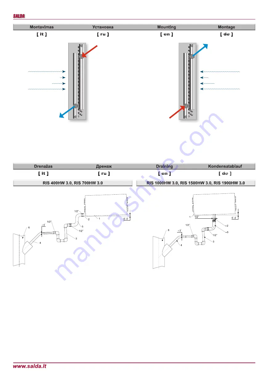
Рекуператор  1  устанавливается  на  осно-

вание  так,  чтобы  сторона  рекуператора  1  с 
трубкой  отвода  конденсата  2    стояла  0  -  3 
градусов  ниже  чем  другая  сторона  (макси-
мальное  значение  показанна  на  рисунке). 
Сторона  рекуператора  1  с  трубкой  отвода 
конденсата не может быть ниже, чем другая 
сторона рекуператора! 

Трубами 4,5 (металлическими, пластиковы-

ми или резиновыми) соедините рекуператор 
1,  сифон  3,  и  канализационную  систему  6. 
Трубы 4,5, должны иметь, не меньше чем 3 
градуса наклона вниз (1 метр трубы должен 
быть наклонен вниз на 55 мм)! Прежде чем, 
включить рекуператор, 1 заполните систему 
не менее 0,5л воды (сифон 3, должен быть 
постоянно  заполнен  водой).  Убедитесь,  что 
вода достигает систему канализации 6, иначе 
при эксплуатации рекуператора 1, помещение 
может быть залито водой!

Система отвода конденсата эксплуатируется 

в помещениях, где температура не достигает 
0°С!  Если  температура  ниже  чем  0°С,  то 
система  отвода  конденсата  должна  быть 
изолированна тепловой изоляцией или обо-
рудован подогрев.

Сифон  3  надо  устанавливать  ниже  чем 

рекуператор 1. 

AHU (1) is built on a foundation in a such way 

that the side of AHU (1) with drainage exhaust 
pipe (2) is lower 0

0

 - 3

0

 than the other side (the 

concrete  max.  value  is  shown  on  the  picture). 
The side of AHU with drainage pipe can not be 
higher than the other side. 

The system must be connected with pipes (4,5) 

in such order: AHU (1), siphon (3) and sewerage 
system  (6).  Pipes  (4,5)  should  be  bended  not 
less than 3° (1 meter of pipe must be bended 
55 mm downwards)! Before turning on AHU (1) 
the draining system should be fi lled up with at 
least 0,5 l of water (siphon (3) must be always 
fi lled  with  water),  also  check  if  water  reaches 
sewerage  system  (6)!  In  other  case  premise 
can be fl ooded. 

Draining  system  must  be  installed  in  the 

premise where the temperature is not lower than 
0°C. If temperature falls below 0°C the draining 
system should be isolated with thermal isolation 
or heating installed. 

The  siphon  (3)  must  be  mounted  below  the 

AHU (1) level.

Das  WRG-Gerät  1  wird  so  auf  dem  Boden 

aufgestellt, dass die Seitenwand des WRG-Ge-
rätes 1 mit dem Auslassrohr des Kondensates 2 
mit 0 - 3 Grad niedriger als die andere Seiten-
wand {maximaler Wert wird im Bild angegeben) 
steht. Die Seitenwand des WRG-Gerätes 1 mit 
dem Auslassrohr  des  Kondensates  darf  nicht 
höher als die andere Seitenwand stehen! Dann 
die  Rohre  (Metall-,  Plastik  oder  Gummirohre) 
4  und  5  sowie  in  angegebener  Reihenfolge 
das  WRG-Gerät  1,  Siphon  3  und  das Abwas-
sersystem  6  zusammenschließen.  Die  Rohre 
4  und  5  sollten  mindestens  mit  einem  Winkel 
von 3 Grad verlaufen (1 Meter es Rohrs sollte 
55mm Gefälle haben). Vor dem Einschalten des 
WRG-Gerätes  1  muss  das  Ablaufsystem  mit 
mindestens  0,5  Liter  Wasser  gefüllt  werden. 
(Der Siphon 3 muss ständig mit Wasser gefüllt 
sein). Kontrollieren Sie, ob das Wasser zum Ab-
wassersystem 6 gelangt. Ansonsten ist während 
des Betriebes des WRG-Gerätes 1 der Austritt 
von Wasser in den Zuluftbereich möglich. Das 
Ablaufsystem  darf  nur  in  Räumen  betrieben 
werden, in welchen die Raumtemperatur nicht 
unter 0°C sinkt! Ansonsten muss das System mit 
thermisch isoliert werden.

Der  Siphon  3  muss  unterhalb  des  WRG-

Gerätes 1 montiert werden.

Rekuperatorius 1 ant pagrindo statomas taip, 

kad  rekuperatoriaus  1  šonas  su  kondensato 
išleidimo vamzdeliu 2 būtų 0 - 3  laipsniais že-
miau už kitą šoną (konkreti maksimali reikšmė 
nurodyta paveikslėlyje). Rekuperatoriaus 1 šo-
nas  su  kondensato  išleidimo  vamzdeliu  negali 
būti aukščiau kito šono!

Vamzdžiais 4,5 (metaliniais, plastikiniais arba 

guminiais) tarpusavyje sujungti nurodyta tvarka 
rekuperatorių 1, sifoną 3 ir kanalizacijos siste-
mą 6. Vamzdžiai 4,5 turi turėti nemažesnį nei 3 
laipsnių kampo nulydį (1 metras vamzdžio turi 
būti  pakrypęs  į  apačią  55mm)!  Prieš  įjungiant 
rekuperatorių  1  reikia  sistemą  užpilti  0,5  litro 
ar  didesniu  vandens  kiekiu  (sifonas  3  turi  būti 
pastoviai  užpildytas  vandeniu)  ir  įsitikinti,  kad 
vanduo patenka į kanalizacijos sistemą 6! Prie-
šingu  atveju  rekuperatoriaus  1  eksploatavimo 
metu galimas patalpų užpylimas vandeniu! 

Kondensato  nuvedimo  sistema  turi  būti  eks-

ploatuojama  patalpose,  kuriose  aplinkos  tem-
peratūra negali būti žemesnė nei 0°C! Jei aplin-
kos  temperatūra  gali  nukristi  žemiau  0°C,  tai 
sistemą  reikia  izoliuoti  šilumine  izoliacija  arba 
įrengti šildymą.

Sifonas  3  turi  būti  žemiau  rekuperatoriaus  1 

lygio.

Vanduo įėj.
Вода вход
Water in
Wasser in

Vanduo išėj.

Вода выход

Water out

Wasser aus

Įeinantis oro srautas
Вход. воздушный поток
Inlet air fl ow
Einlass-Luftstrohm

Vanduo įėj.
Вода вход
Water in
Wasser in

Vanduo išėj.

Вода выход

Water out

Wasser aus

Įeinantis oro srautas

Вход. воздушный поток

Inlet air fl ow

Einlass-Luftstrohm

Summary of Contents for RIS 400HW 3.0

Page 1: ...sign sind vorbehalten Subject to technical modi cation REKUPERATORINIAI RENGINIAI AHU WITH HEAT RECOVERY L FTUNGSGER TE MIT W RMER CKGEWINNUNG RIS 400HW 3 0 RIS 700HW 3 0 RIS 1000HW 3 0 RIS 1500HW 3 0...

Page 2: ...aptarnaudami rengin naudokite speciali darbin aprang B kite atsarg s renginio ir j sudaran i j dali kampai ir briaunos gali b ti a trios ir eid ian ios alia renginio ned v kite plev suojan i drabu i k...

Page 3: ...des Kondensates darf nicht h her als die andere Seitenwand stehen Dann die Rohre Metall Plastik oder Gummirohre 4 und 5 sowie in angegebener Reihenfolge das WRG Ger t 1 Siphon 3 und das Abwas sersyste...

Page 4: ...Au enluft lter IF Abluft lter TJ Zulufttemperaturf hler M by pass Klappe M1 Regelungseinheit mit motor extra bestellbar Tiekiamas oras Supply air Zuluft I traukiamas oras Extract air Abluft vie ias or...

Page 5: ...nti atjungto ir i imto ildytuvo vamzdeli sandarum suspaustu oru Checking Check performance of thermal circulation Temporary increase water temperature for this Check tightness of water supply system C...

Page 6: ...consequential expense and loss nor does this warranty apply to equipment where alterations have been executed without our knowlege or consent These conditions are readily discern able when the equipme...

Page 7: ...iekimo supply zuluft galia srov power current Nennleistung Nennstrom kW A apsisukimai speed Drehzahl min 1 apsaugos klas protection class Schutzart Pajungimo vamzd io skersmuo Connection pipe diameter...

Page 8: ...otis Width Breite L mm Auk tis Height H he H mm Gylis Depth Tiefe L2 mm Filtro modelis Filter model Filter Modell G4 G4 M5 M5 M5 250 400 538 538 688 226 224 384 384 505 170 210 270 270 280 M5 M5 M5 M5...

Page 9: ...egelt werden Die durch den Benutzer eingestellte Zulufttemperatur wird durch den Platten od Rotor W rmetauscher und oder einen zus tzlichen Elektro od Wasserheizer wird als Zusatz bestellt beibehalten...

Page 10: ...way thyristor module ESKM these modules are installed only in heaters connected to the three phase mains Cooling by ventilation Two types of cooling exist using halocarbon or water cooler Cooling is b...

Page 11: ...button and the device is restarted When heater fault is registered manual heater protection can be restored only after estimation of the fault cause and only if it is safe to do so regardless of the...

Page 12: ...the FLEX installer description Fig 3 RS485_1 and RS485_2 RS485_1 remote control panel socked RS485_2 Mod Bus port RJ11 socket contacts reference 1 COM 2 A 3 B 4 24V Microswitches 1 and 2 Fig 4 are mou...

Page 13: ...erat ros jutiklio pavojaus signalas ru en Supply air temperature sensor alarm de Zuluft Temperatursensor Alarm 1 active o passive 9 RH 01h_Read_Coils 9 1 lt DTJ 100 dr gnumo jutiklio pavojaus signalas...

Page 14: ...ei renginio maitinimo linija yra toli nuo agregato b tina vertinti atstum ir tampos kritim renginys b tinai turi b ti emintas Sumontuokite valdymo pulta numatytoje vietoje Nutieskite pajungimo kabel e...

Page 15: ...RIS 400H V P 3 0 6mF 400V When the RIS 700H V P 3 0 5mF 400V When the RIS 260V 3 0 1 5 mF 400V When the RIS 400H V P 3 0 6mF 400V When the RIS 700H V P 3 0 5mF 400V valve actuator Water cooler 1 3 2...

Page 16: ...11 12 13 14 15 16 17 N 19 X16 5 M2 M3 17 18 L N N L L 16 20 15 230V AC 230V AC ON OFF ON OFF L control N L control L Supply air Extract air damper actuator damper actuator Fire alarm input X16 25 24...

Page 17: ...water heater is used it is necessary to prop erly install antifreeze protection from possible freezing of heat carrier Antifreeze temperature sensor TV must be mounted in clamp on return pipe of the...

Page 18: ...Schalter F eingeschaltet sind Sicherung des RG1 Reglers 250 mA pr fen Gedimas agregato elektros sujungimuose jungtyse Possible unit fault at electrical connections of the unit St rung in elektrischen...

Page 19: ...eikia ventiliatorius iai Fan s not working Ventilator en nicht funktioniert Tiekiamo PV arba i traukiamo IV oro ventiliato riaus gedimas PV IV Supply PV or extracted IV air fan fault St rung des Venti...

Page 20: ...pply voltage Disconnect the respective sensor plug from the automation Measure and check the sensor voltage using the bellow dependency Fig 1a If measure ment results do not correspond with the given...

Page 21: ...RIS HW 3 0 21...

Page 22: ...ektrinis ildytuvas Electric heater Elektroheizer O 16A 100 X29 Elektrinis pa ildytuvas rotorius Electric preheater rotor ON OFF 230V 50Hz Elektrovorheizer Rotor EIN AUS 230V 50Hz O 16A 100 X12 Esamo g...

Page 23: ...Freoninio au intuvo arba vandeninio ildytuvo cirkuliacinio siurblio valdymas DX cooler or water heater circulatory pump control Kontrollieren des Freonk hlers bzw der Zirkulationspumpe von der Wasser...

Page 24: ...ler X38 1 I trukiamo oro temperat ros jutiklis Extract air temperature sensor Abzugsluft Temperatursensor AI X38 2 COM X40 1 5V X40 2 I traukiamo oro santykin s dregm s jutiklis Extract air humidyti s...

Page 25: ...rmin ap i r Jei tiesioginis pirk jas nustato kad ventiliacin ranga neveikia ar turi defekt jis per 5 darbo dienas turi kreiptis gamintoj nurodydamas kreipimosi prie ast bei pristatyti rang gamykl u sa...

Page 26: ...set COM X33 21 X33 22 BK Black BN Brown BU blue RD red X33 7 X33 8 DMP DMP 24VDC 24VDC X41 1 X41 2 X39 2 X39 1 X38 1 X38 2 X40 3 X40 2 X40 1 X34 8 X34 7 X34 6 X34 5 X34 4 X34 3 X34 2 X34 1 X33 26 X33...

Page 27: ...set COM X33 21 X33 22 BK Black BN Brown BU blue RD red X33 7 X33 8 DMP DMP 24VDC 24VDC X41 1 X41 2 X39 2 X39 1 X38 1 X38 2 X40 3 X40 2 X40 1 X34 8 X34 7 X34 6 X34 5 X34 4 X34 3 X34 2 X34 1 X33 26 X33...

Page 28: ...X35 4 X35 5 X10 X33 6 X8 RS485_1 RG1 TA 13 14 LOW X32 1 COM X32 4 HIGH X32 2 TIME X32 3 COM X33 15 MIDL X33 2 CHIL X33 9 COM X33 10 BOOST STOP NO START NC A2 A1 R1 8 7 X16 3 ALARM X33 11 COM ANTI F F...

Page 29: ...T NC STOP NO BOOST X33 10 COM X33 9 CHIL X33 2 MIDL X33 15 COM X32 3 TIME X32 2 HIGH X32 4 COM X32 1 LOW 14 13 TA RG1 RS485_1 X8 X33 6 X10 X35 5 X35 4 X35 3 X33 21 X33 22 X33 20 X33 19 A3 A3 A2 A2 A1...

Page 30: ...XC2 XC2 XC1 XC1 15 X16 2 HR A4 A4 PUMP AC N X4 X3 ModBus RTU RS485_2 RS485_2 A1 A1 A2 A2 A3 A3 TE TE X52 X33 19 X33 20 COM T WAT TJ X33 22 X33 21 X35 3 X35 4 X35 5 N L supply L control N N N EXT EXT...

Page 31: ...da lt www salda lt I rad j g 13b 78149 iauliai Tel 8 41 540212 Faks 8 41 596176 prekyba salda lt J Kazlausko g 21 08314 Vilnius Tel 8 5 2733538 Faks 8 5 2753007 vilnius salda lt Elektr n g 8 51221 Kau...

Page 32: ...er replacement Filter Ersatz Kas 3 4 m nesius 3 4 Every 3 4 months Alle 3 4 Monate PASTABA Produkt sigij s asmuo privalo pildyti Gaminio prie i ros lentel NOTE The purchaser is required to ll in the P...

Reviews: